

Sliding member
a technology of sliding member and sliding shaft, which is applied in the direction of shaft and bearing, bearing, bearing, etc., can solve the problem of extremely small leakage amount, and achieve the effect of easy formation of negative pressure generation mechanism
- Summary
- Abstract
- Description
- Claims
- Application Information
AI Technical Summary
Benefits of technology
Problems solved by technology
Method used
Image

Examples
first embodiment
[0047]Hereinafter, an exemplary mode for carrying out this invention will be described based on an embodiment with reference to the drawings. Note that unless otherwise clearly described, the dimensions, materials, shapes, and relative arrangement of components described in this embodiment are not intended to limit the claims of the present invention.
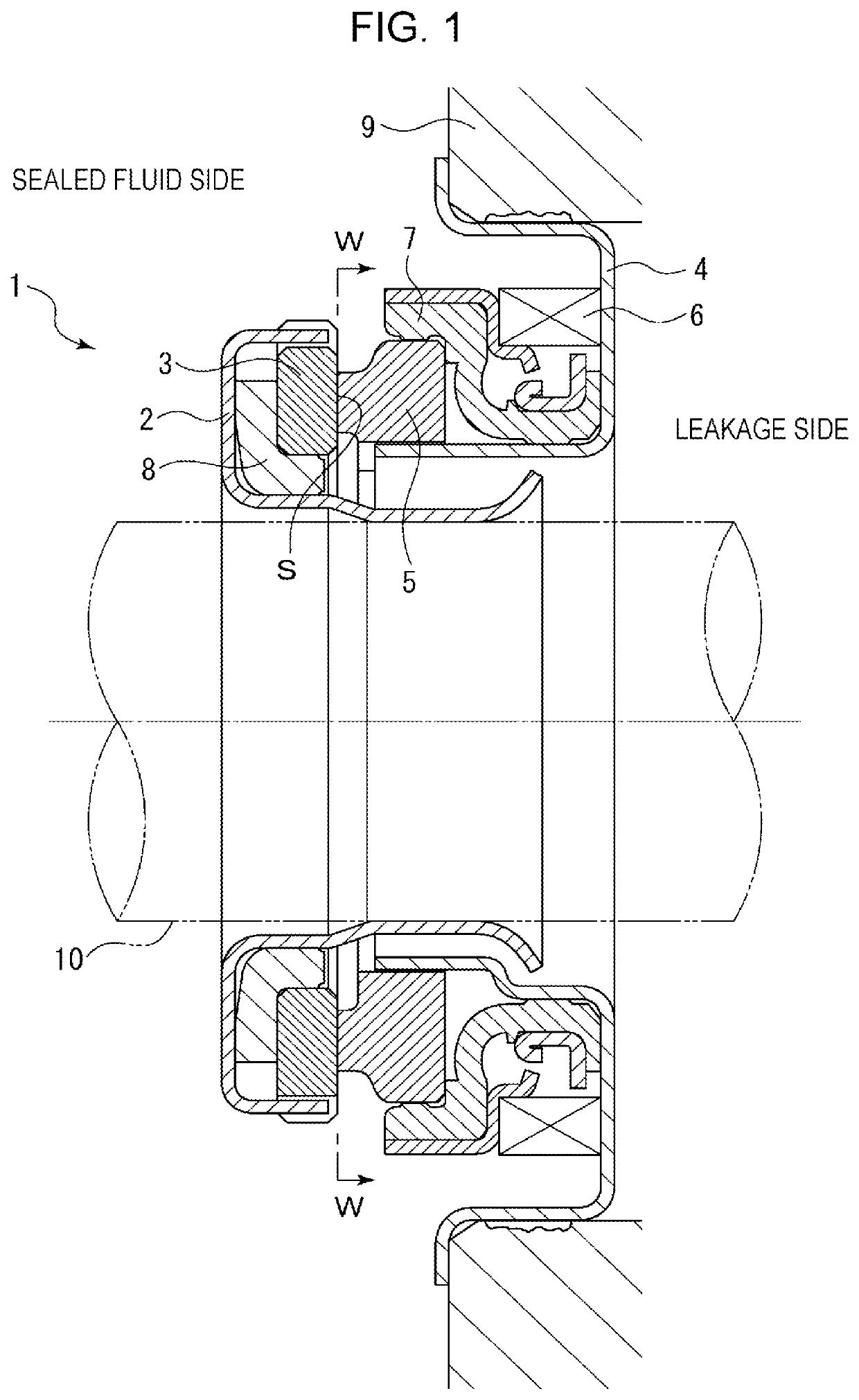
[0048]A sliding member according to a first embodiment of the present invention will be described with reference to FIGS. 1 and 2. Note that in the first embodiment, a mechanical seal as one example of the sliding member will be described. In the first embodiment, an outer peripheral side of the sliding member forming the mechanical seal will be described as a sealed fluid side (a high-pressure fluid side), and an inner peripheral side will be described as a leakage side (a low-pressure fluid side).
[0049]FIG. 1 is a longitudinal sectional view showing one example of the mechanical seal 1, and shows an inside mechanical seal configured t...
second embodiment
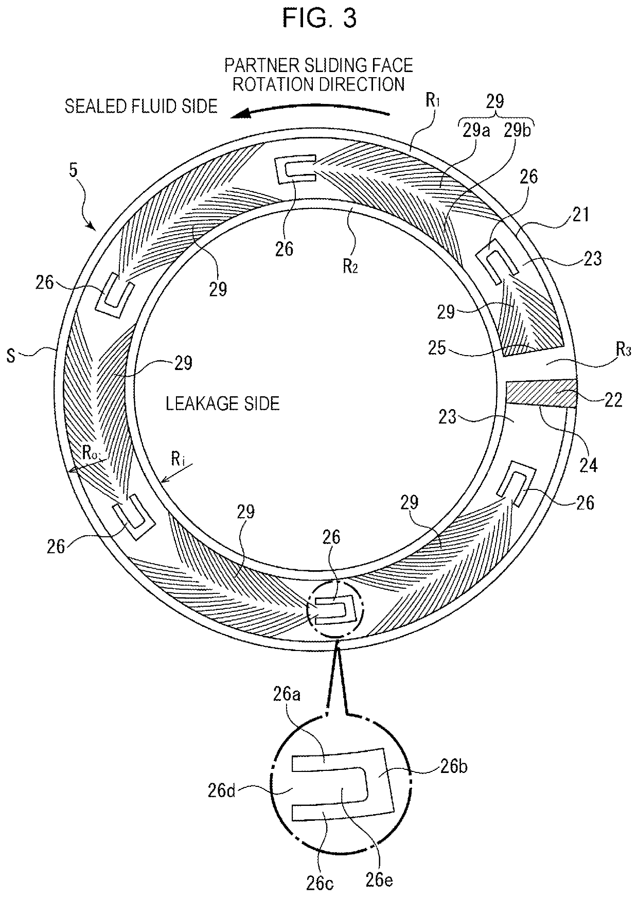
[0064]A sliding member according to a second embodiment of the present invention will be described. FIG. 3 shows a sliding face S of the sliding member according to the second embodiment. FIG. 3 is different from the first embodiment in that a guide groove 29 is provided, but is the same as the first embodiment in other configurations. Hereinafter, the same reference numerals are used to represent the same members as those of the first embodiment, and overlapping description will be omitted.
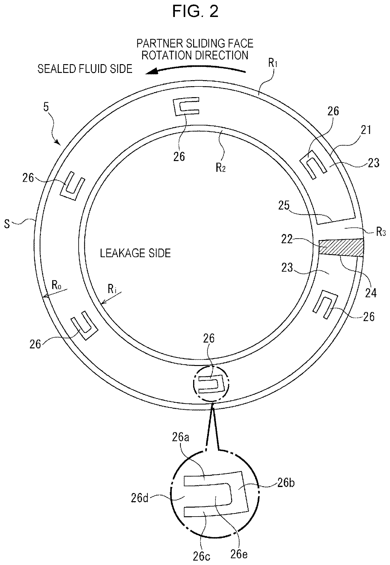
[0065]As shown in FIG. 3, a sliding face S of a stationary-side seal ring 5 includes a negative pressure generation mechanism 21. The negative pressure generation mechanism 21 includes a fluid introduction groove 22 communicated with a sealed fluid side and an annular groove portion 23 having an opening 24 communicated with the fluid introduction groove 22 on a downstream side and a dead end portion 25 surrounded by a sealed-fluid-side land portion R1, a leakage-side land portion R2, and a radial...
third embodiment
[0081]A sliding member according to a third embodiment of the present invention will be described. FIG. 5 shows a sliding face S of the sliding member according to the third embodiment. FIG. 5 is only different from the second embodiment in the shape of a land portion 36 and the configuration of a guide groove 39, and is the same as the second embodiment in other configurations. Hereinafter, the same reference numerals are used to represent the same members as those of the second embodiment, and overlapping description will be omitted.
[0082]As shown in FIG. 5, a sliding face S of a stationary-side seal ring 5 includes a negative pressure generation mechanism 31. The negative pressure generation mechanism 31 includes a fluid introduction groove 32 communicated with a sealed fluid side and an annular groove portion 33 having an opening 34 communicated with the fluid introduction groove 32 on a downstream side and a dead end portion 35 surrounded by a sealed-fluid-side land portion R1,...
PUM
 Abstract
Description
Claims
Application Information