Centrifuging system, sample preprocessing system, and control method

a sample preprocessing and centrifuging technology, applied in centrifuges, separation processes, instruments, etc., can solve the problems of inability to efficiently process samples, inability to save labor and speed up examination work, and insufficient contribution of sample preprocessing systems to labor saving and rapid examination work. , to achieve the effect of minimizing the processing time and improving the processing tim

Active Publication Date: 2015-12-17
HITACHI HIGH-TECH CORP
View PDF35 Cites 12 Cited by
  • Summary
  • Abstract
  • Description
  • Claims
  • Application Information

AI Technical Summary

Benefits of technology

[0011]A system management unit ascertains states of a plurality of centrifuge devices, and thus it is possible to particularly expect an effect of improving a processi...

Problems solved by technology

Regarding the rapidness of examination reporting, preprocessing work such as centrifuging, the unplugging of a blood collection tube, dispensing for subdividing a sample for each necessary examination, and distribution which are preprocessing steps of sample examination accounts for the majority of an examination time, and thus a reduction in time required for the preprocessing work has become a major problem.
For this reason, when the centrifuge device is incorporated into th...

Method used


Image

  • Centrifuging system, sample preprocessing system, and control method
  • Centrifuging system, sample preprocessing system, and control method
  • Centrifuging system, sample preprocessing system, and control method

Examples


first embodiment

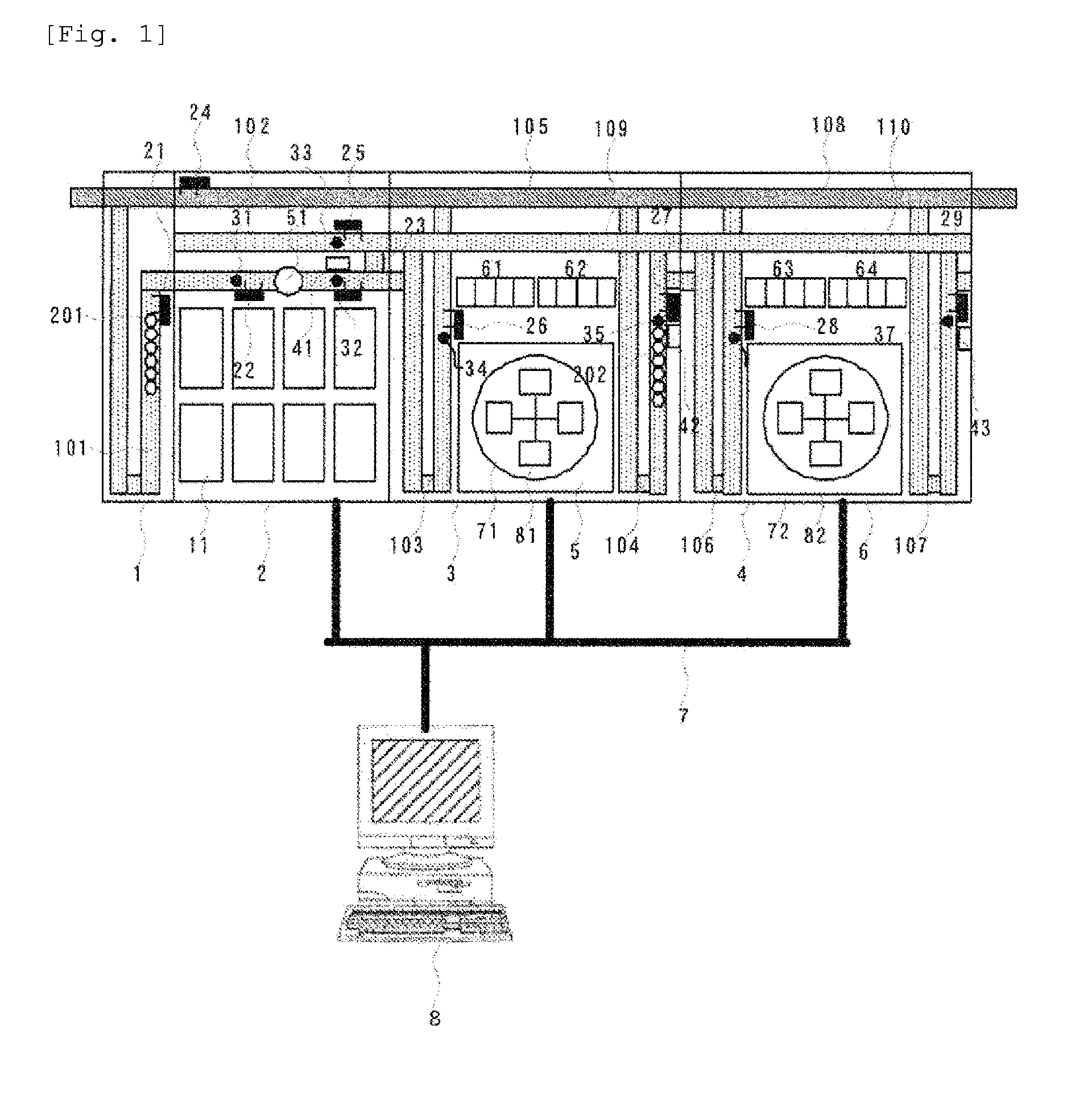
[0026]FIG. 1 schematically illustrates a portion of a sample processing system according to an embodiment of the invention. The system includes the centrifuge module 3 and a centrifuge module 4.

[0027]The sample input module 2 has a position capable of installing a plurality of sample input trays 11 accommodating a plurality of samples. When samples input by the sample input trays 11 are detected, a sample chuck mechanism not shown in the drawing transfers each of the samples to a holder. In this system, a method of mounting the sample on the holder and conveying the holder having the sample to each processing unit is adopted. A vacant holder for mounting the sample stands by on a vacant holder standby line 101 and is conveyed to a position for placing the sample when detecting the installation of a new tray.

[0028]An RFID 31 tag of a conveyed holder 201 is read by an RFID 31, and thus it is possible to individually identify vacant holders 201. Samples input from the sample input modu...

second embodiment

[0076]A second embodiment of the invention will be described below.

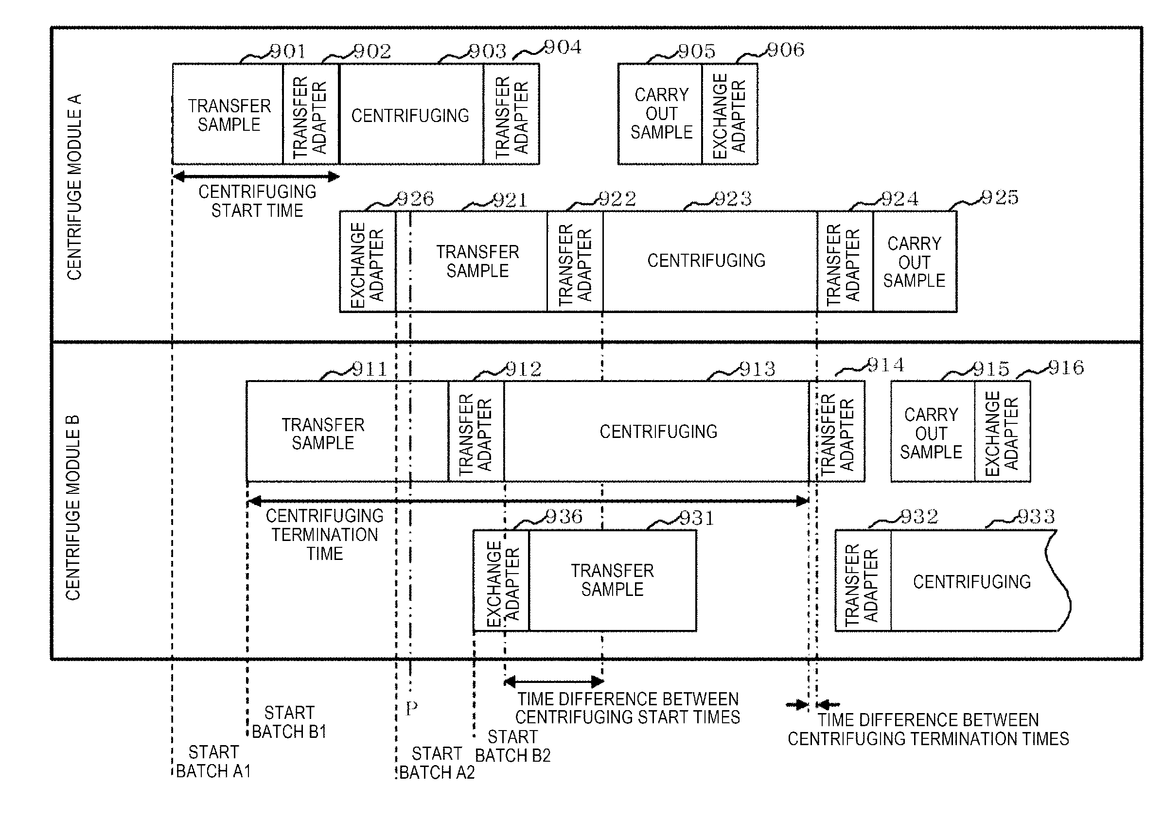
[0077]When there are small differences between “centrifuging start times” of batches and between “centrifuging termination times” thereof, it is considered that the preferential conveyance of a sample from a centrifuge module positioned on the downstream side leads to a reduction in the occupancy rate of a conveyance line in a centrifuge module portion and thus contributes to a reduction in congestion of a holder having samples mounted thereon. In this case, in addition to the centrifuging start time determination step 609 and the centrifuging termination time determination step 611 of FIG. 3, a difference between a centrifuging start time (centrifuging termination time) which is already set and a centrifuging start time (centrifuging termination time) compared therewith this time is also examined. Only when the time difference is equal to or greater than a threshold value, are the “centrifuging start time” and the “...

third embodiment

[0078]Another embodiment of the invention will be described below.

[0079]Focusing on a sample input interval of a sample input module, the standby time-out 726 is not likely to occur during predetermined sample transfer processes 901, 911, 921, and 931 in a time period having a large number of samples from morning to afternoon, and thus sample arrival standby is not likely to occur when seen from a centrifuge module.

[0080]However, in a time period in which the number of samples is decreased (since afternoon), the standby time-out 726 is expected to frequently occur, and thus it is considered that centrifuging is started in a state where the centrifuge adapters 61 and 63 on the carry-in side do not become full. Further, since only several samples arrive per an hour in operation in the evening and night, an excessive standby time is generated not only in the standby time-out 726 for a general sample of FIG. 6 but also in the sample standby time-out 728 for an urgent sample, and thus it...


PUM

PropertyMeasurementUnit
Timeaaaaaaaaaa

Abstract

A sample preprocessing system is capable of reducing centrifuging time, which accounts for the majority of time required for a preprocessing step, and at the same time, performing centrifuging under various conditions. A system management unit ascertains the states of a plurality of centrifuge devices, particularly comparing centrifuging start times and centrifuging termination times for the respective centrifuge devices, and selects the centrifuge device for which the processing time is shortest. Specifically, the system includes an adapter that forms a plurality of batches, sample transfer means for transferring a sample to the adapter, a plurality of centrifuge rotors that centrifuge the adapter in batch units, and calculation means for calculating in advance a start timing and a termination timing of the centrifuging in batch units, and the batch, into which samples are transferred, is controlled on the basis of at least one of the calculated start timing and termination timing.

Description

TECHNICAL FIELD[0001]The present invention relates to a centrifuging system that automatically centrifuges a sample, and a control method thereof.BACKGROUND ART[0002]In a recent clinical examination field, the labor saving of examination work has been achieved by introducing various types of automation apparatuses and examination systems. In addition, in university hospitals and the like, has become widespread examination before medical care by the reduction in an examination reporting time. In an examination before medical care, a process of collecting samples such as blood and urine from a patient and then reporting an examination result is performed within approximately one hour. Regarding the rapidness of examination reporting, preprocessing work such as centrifuging, the unplugging of a blood collection tube, dispensing for subdividing a sample for each necessary examination, and distribution which are preprocessing steps of sample examination accounts for the majority of an ex...

Claims


Application Information

Patent Timeline
IPC IPC(8): B04B5/00G01N35/02B04B13/00
CPCB04B5/00B04B2011/046G01N35/02B04B13/00G01N35/0092G01N2035/00495G01N2035/0094B04B5/10
Inventor YANO, SHIGERUWATABE, OSAMUTAKAHASHI, KENICHISASAKI, TAKAHIRO
Owner HITACHI HIGH-TECH CORP
Why Eureka
Try Eureka