Centrifugal separator

a centrifugal separator and separator technology, applied in the direction of centrifuges, engine seals, rotary centrifuges, etc., can solve the problems of high wear, mechanical sealing liquid is required for expensive equipment, and the mechanical sealing is subject to wear and tear. , to achieve the effect of improving mechanical sealing, improving life and proper sealing ability

Inactive Publication Date: 2009-11-12
ALFA LAVAL CORP AB
View PDF10 Cites 12 Cited by
  • Summary
  • Abstract
  • Description
  • Claims
  • Application Information

AI Technical Summary

Benefits of technology

[0006]The object of the invention is to remedy the problems mentioned above and to provide a centrifugal separator with an improved mechanical seal. More specifically, the object is a centrifugal separator having a mechanical seal with improved life and proper sealing ability.

Problems solved by technology

One problem with available mechanical seals is to provide a sufficient abutment force between the two contact surfaces so that an efficient sealing of the gap is achieved during all operating conditions.
A further problem with available mechanical seals is the wear which they are subjected to.
In particular, when the centrifugal separator is started and before any liquid is available at the mechanical seal, the contact surfaces of the seal will slide against each other in a dry state, which results in high wear.
In order to solve this problem, expensive equipment is required for supplying sealing liquid to the mechanical sealing.

Method used


Image

  • Centrifugal separator
  • Centrifugal separator
  • Centrifugal separator

Examples


Embodiment Construction

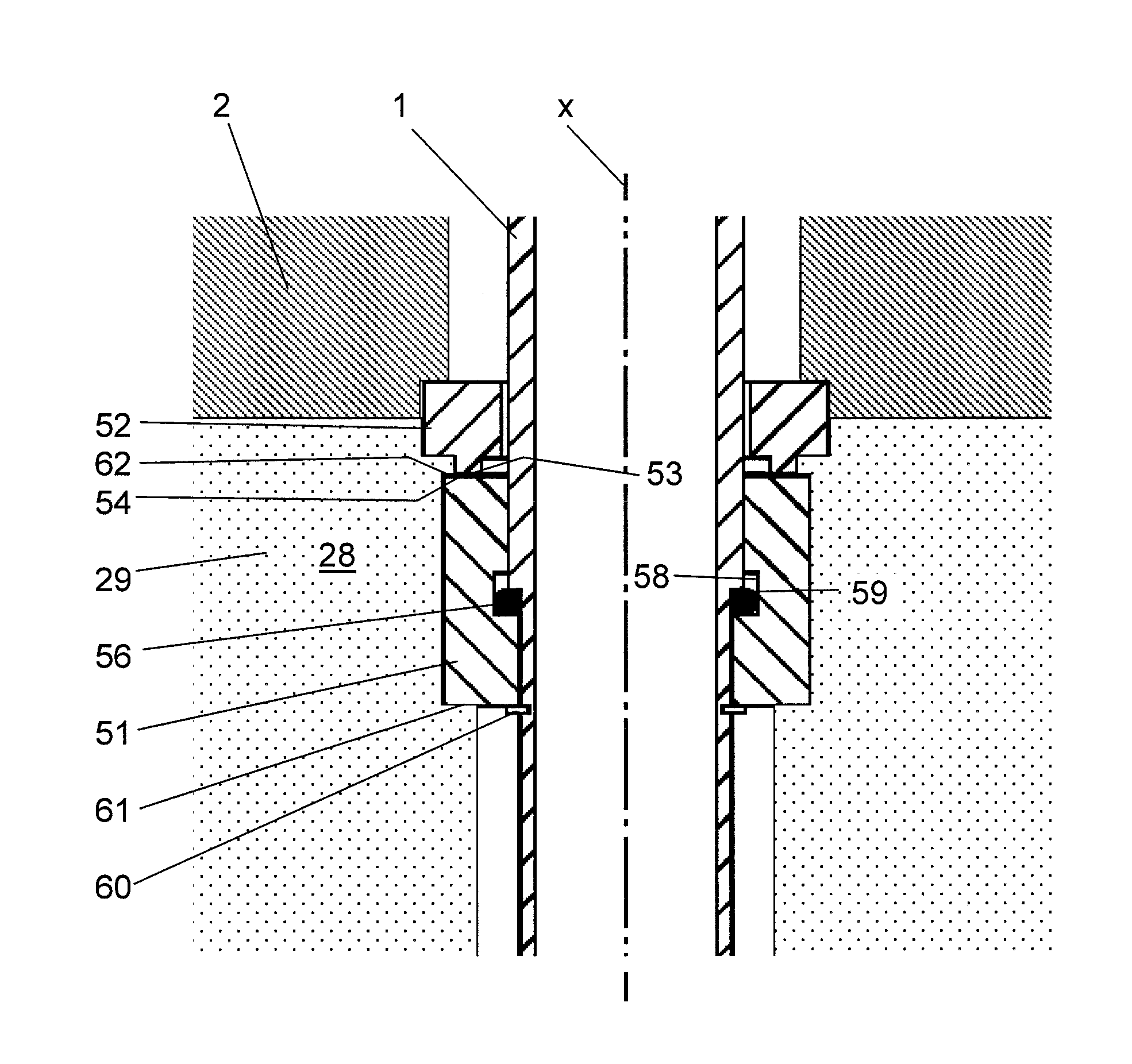
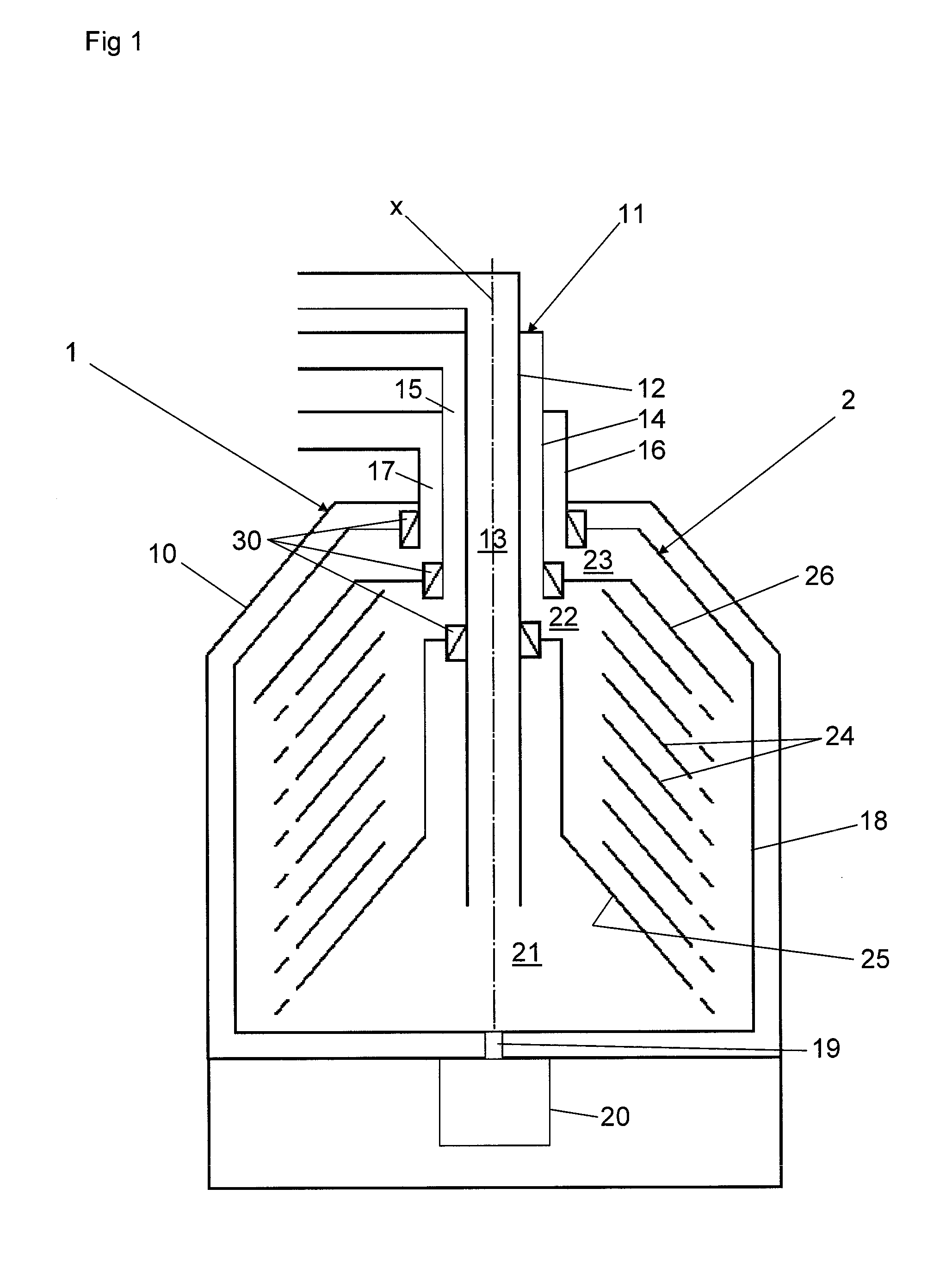
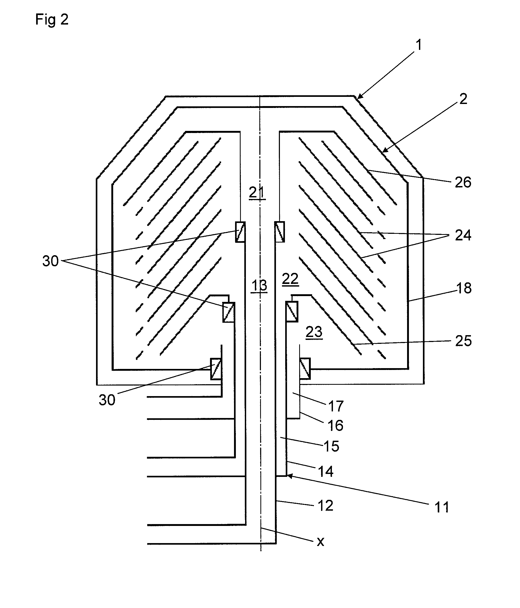
[0024]FIG. 1 discloses schematically a centrifugal separator for separation of at least two phases of a medium. The centrifugal separator comprises a first separator part 1 and a second separator part 2.

[0025]In the first embodiment, the first separator part 1 comprises a stationary casing 10 and a stationary inlet and / or outlet member 11 which comprises a first pipe 12, which encloses a first channel 13 for feeding of the medium to be separated, a second pipe 14, which encloses a second channel 15 for discharging a relatively light phase of the medium, and a third pipe 16, which encloses a third channel 17 for discharging a relatively heavy phase of the medium.

[0026]The second separator part 2 comprises a centrifuge rotor 18 and a spindle 19, which are driven to rotate about an axis x of rotation by means of a suitable drive member 20, for instance an electric motor. The second separator part 2, i.e. the centrifuge rotor 18, is arranged to be driven at a determined high speed of ro...


PUM


Abstract

In a centrifugal separator comprising a first and second separator part having a centrifuge rotor and rotates during operation relative to the first separator part. A space connecting the first and second separator parts houses a rotating liquid body during operation. A mechanical sealing device is provided at the space and includes a first sealing element on the first separator part having a first contact surface, and a second sealing element on the second separator part having a second contact surface. The liquid body on the first sealing element or the second sealing element and displaces the same axially so that the first and second contact surfaces are pressed against each other. A pre-tensioning element exerts force on the sealing element which acts to displace the first contact away from the second contact surfaces so that a gap is formed, forming a throttling.

Description

FIELD OF THE INVENTION[0001]The present invention refers to a centrifugal separator and more particularly to sealing devices used therewith.BACKGROUND OF THE INVENTION[0002]In centrifugal separators there is a need for efficient mechanical sealings in several different positions, i.e. mechanical sealings which are suitable for sealing a gap between a rotating separator part and a stationary separator part, or between two rotating separator parts rotating at different speeds, for instance in decanter centrifuges.[0003]In for instance so-called hermetic centrifugal separators, mechanical sealing is required between the rotating centrifuge rotor and a stationary inlet and / or outlet pipe extending into the centrifuge rotor. Furthermore, one or several mechanical seals are required between a stationary connection housing and a rotating inlet and / or outlet pipe connected to and communicating with the interior of the centrifuge rotor.[0004]One problem with available mechanical seals is to ...

Claims


Application Information

Patent Timeline
Patent Type & Authority Applications(United States)
IPC IPC(8): B04B15/08
CPCB04B7/00B04B1/08B04B11/02B04B9/12F16J15/16F16J15/34F16J15/164F16J15/3448F16J15/346
Inventor KLINTENTEDT, KJELL
Owner ALFA LAVAL CORP AB
Why Eureka
Try Eureka