Mechanical seal and mechanical seal device

a mechanical seal and mechanical technology, applied in the direction of mechanical seals, pipe elements, mechanical apparatus, etc., can solve the problems of slack between the base end and the drive pin, difficult to effectively obtain a good mechanical seal, and drive pin bending, etc., to achieve shorten the length of the drive pin, reduce the strength, and simplify the effect of miniaturization

Active Publication Date: 2010-10-19
NIPPON PILLAR PACKING CO LTD
View PDF5 Cites 10 Cited by
  • Summary
  • Abstract
  • Description
  • Claims
  • Application Information

AI Technical Summary

Benefits of technology

[0013]According to the mechanical seal and mechanical seal device of the invention, since the drive pin engaging with the stationary sealing ring is supported to the case body on both sides of the engaged portion thereof, the problems which occur in the cantilever-supported drive pin as described in introduction do not occur, the drive pin function (the rotary prevention function of the stationary sealing ring by means of the drive pin) is stably achieved, and the mechanical seal or mechanical seal device can be preferably operated for long periods. Further, since the drive pin made of a metal or plastic material having a lower strength than the metal can be used, it may be preferably used in a situation that requires prevention of contamination. Accordingly, the usage of the mechanical seal device can be considerably extended.
[0014]In addition, according to the mechanical seal in which a plurality of the mechanical seals is disposed in parallel, since the drive pin of all of the mechanical seals is commonly used by the drive bar, the structure of mechanical seal device can be considerably simplified as compared with the case in which the drive pins are provided in mechanical seals, respectively. Accordingly, the manufacture of the mechanical seal device has a considerable advantage in terms of lowering manufacturing cost.

Problems solved by technology

However, in a mechanism which prevents the rotation of such stationary sealing ring by the drive pin, since the drive pin is only cantilever-supported to the case body, it is difficult to effectively obtain a good mechanical seal during long terms, and following problems occur.
That is, since the base end of the drive pin is only screwed or press-fitted into the screwed hole or press-fitted hole formed in the case body, when a bending moment is applied to the front end engaging with the stationary sealing ring, it has a problem that a slack occurs between the base end and the screwed hole or press-fitted hole, and the drive pin is bended.
With the above described state, the sealing function is not adequately realized by the relative rotation of both the stationary sealing ring and the rotary sealing ring.
In addition, if the drive pin is continuously used with such state, the drive pin tends to detach from the case body, and the base end of the drive pin which is screwed or press-fitted into the screwed hole or the press-fitted hole becomes damaged and broken.
As a result, since the function of the drive pin is completely lost, the sealing function cannot be realized.
Therefore, if the function of the drive pin is lost, it requires that all the mechanical seals be replaced or repaired.
Such problems are especially prominent in the mechanical seal device such as a multi-flow channel type rotary joint in which a plurality of the mechanical seals is juxtaposed.
The reason is that a functional deterioration and loss of the drive pin in one mechanical seal is directly associated with the function deterioration and loss of the overall mechanical seal device.
Therefore, since the drive pin could be not applied to a situation in which a fluid contacting with the drive pin and metal ions should not be mixed, it has the problem that the use of the drive pin is considerably limited (For example, the mechanical seal used in a rotary equipment such as a surface polishing device for polishing semiconductor wafers by CMP (Chemical Mechanical Polishing) method, which requires a steps to prevent a high contamination).

Method used


Image

  • Mechanical seal and mechanical seal device
  • Mechanical seal and mechanical seal device
  • Mechanical seal and mechanical seal device

Examples


Embodiment Construction

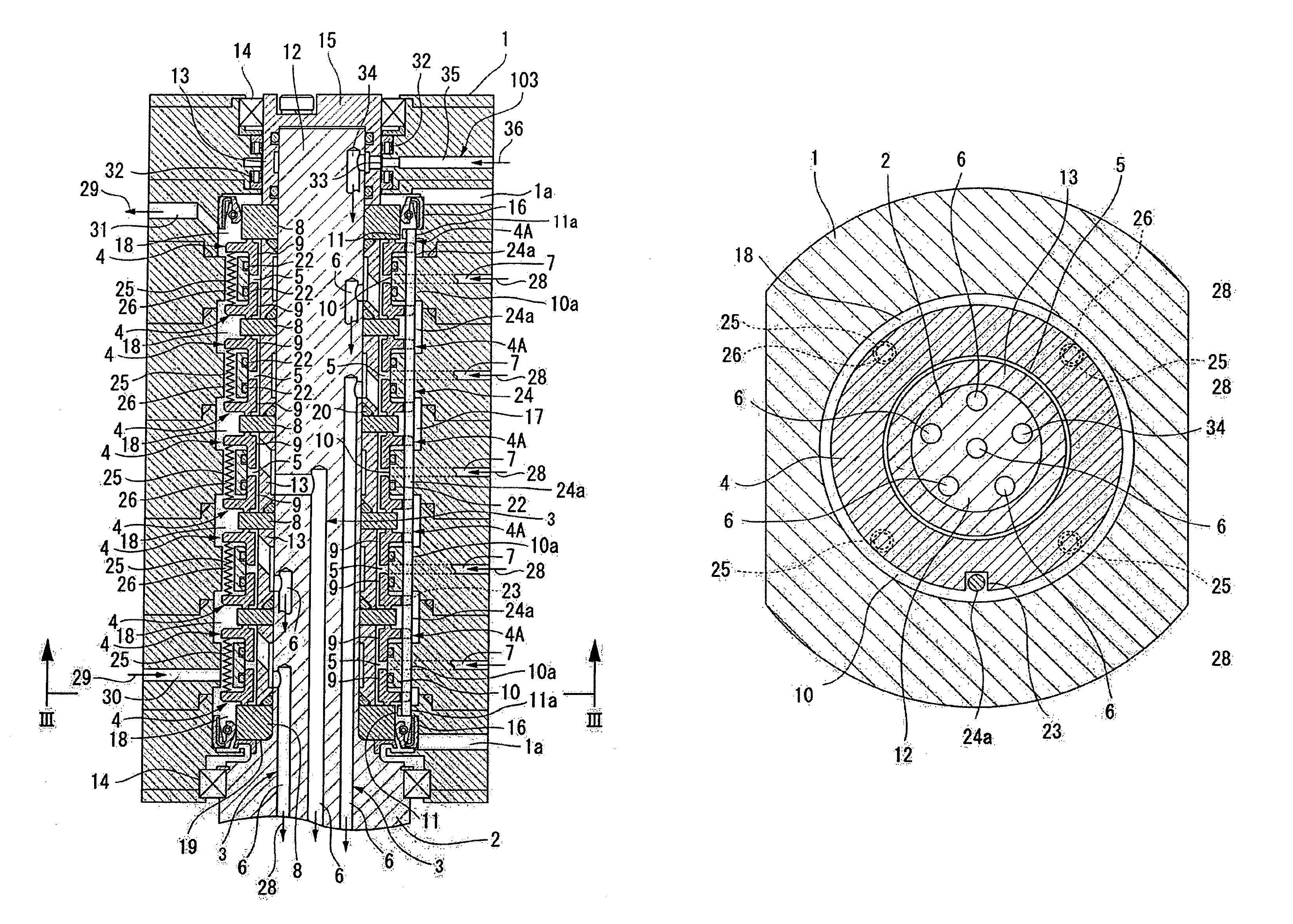
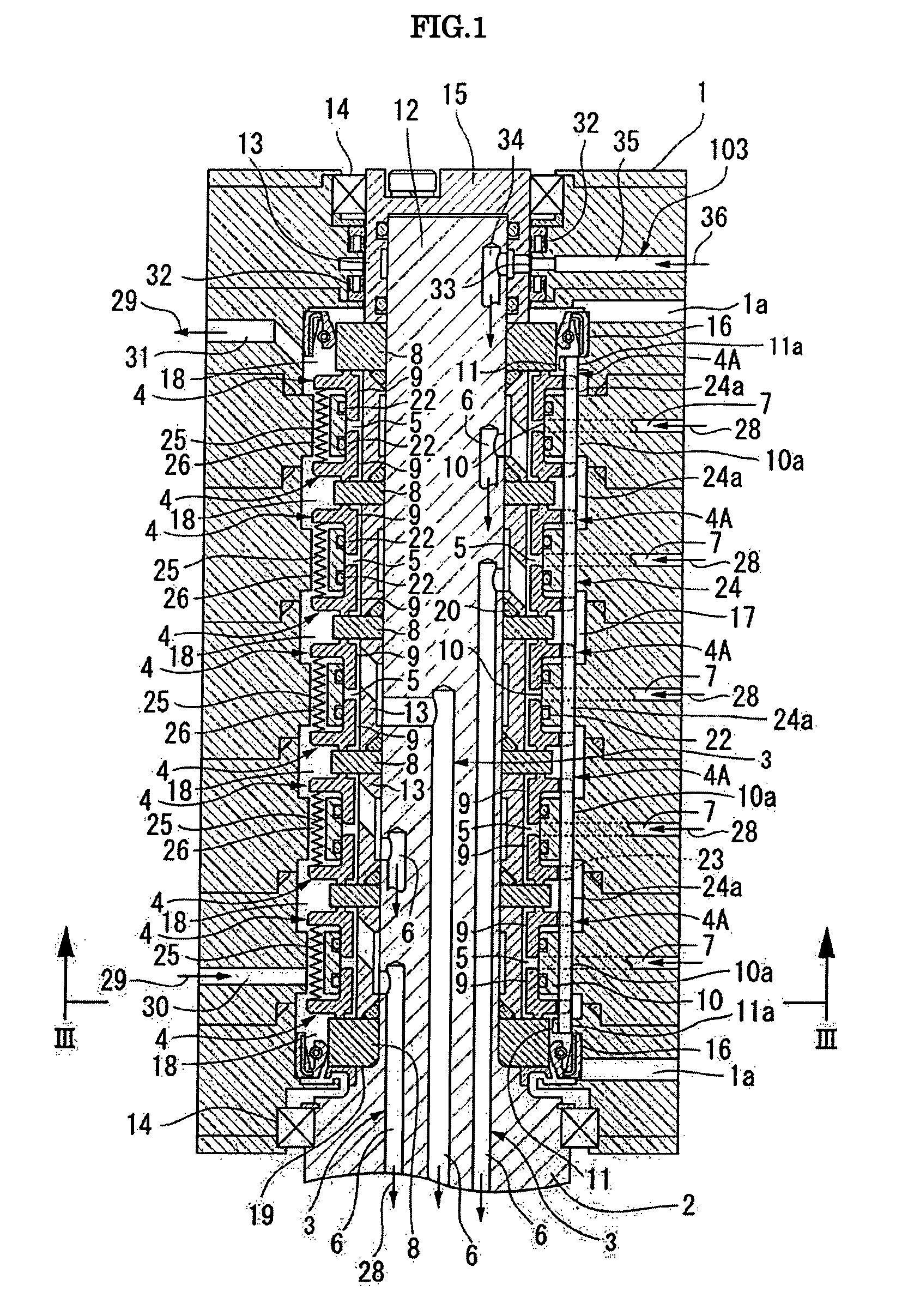
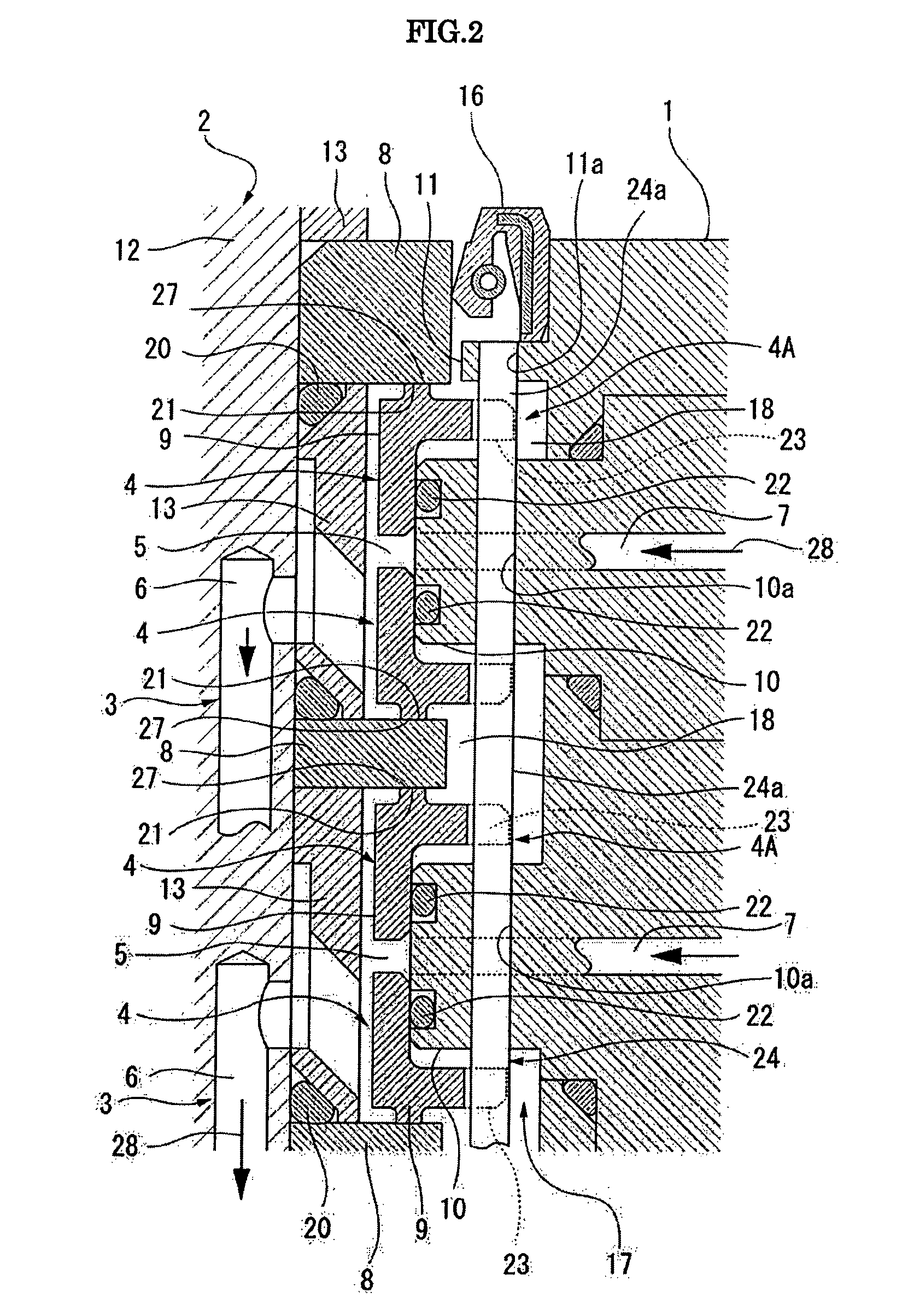
[0040]FIG. 1 is a front cross-sectional view showing a rotary joint, an example of a mechanical seal device according to the invention, FIG. 2 is an enlarged front cross-sectional view showing the mechanical seal according to the invention, which is used in the rotary joint, and FIG. 3 is a traverse bottom view of the rotary joint (the cross section is taken along line III-III in FIG. 1). Further, a top and bottom referred to a following description imply the top and bottom in the FIGS. 1 and 2.

[0041]The mechanical seal device shown in FIG. 1 is a multi-flow channel type rotary joint which allows a plurality of fluids to flow between a main body of the device serving as a stationary-side member and a top ring or turn table serving as a rotary-side member in a CMP apparatus.

[0042]That is, as shown in FIG. 1, the rotary joint includes a tubular case body 1 mounted on the stationary-side member (main body of the CMP apparatus) and a rotary shaft body 2 mounted on the rotary-side member...


PUM


Abstract

A mechanical seal 4 includes a rotary sealing ring 8 which is fixed to a rotary shaft body 2 and a stationary sealing ring 9 which is movably held to a tubular case body 1 in an axial direction thereof, and seals a space between inner and outer peripheral areas 5 and 18 of a relative rotation portion by means of the relative rotation of opposite end faces 21 and 27 of both sealing rings 8 and 9. A drive pin 24a which is engaged with a recessed portion 23 formed in an outer periphery of the stationary sealing ring 9 is fixedly supported to the case body 1 at both sides of a place engaging with the recessed portion 23 so as to prevent the stationary sealing ring 9 from rotating relatively to the case body 1. The drive pin 24a is made of a metal or plastic material according to the conditions of use. The rotary prevention function of the stationary sealing ring 9 is stably achieved by the drive pin 24a, and the plastic material that enables to prevent a contamination may be used as the constituting material of the drive pin 24a.

Description

TECHNICAL FIELD[0001]The present invention relates to a mechanical seal and a mechanical seal device such as a rotary joint in which a plurality of the mechanical seals are juxtaposed in an axial direction thereof.BACKGROUND ART[0002]There has been well known that a mechanical seal having a rotary sealing ring which is fixed to a rotary shaft body (such as a rotary shaft) rotatably driven and a stationary sealing ring which is movably held to a tubular case body (such as a seal case through which a rotary shaft concentrically penetrates) in an axial direction so as to seal the space between inner and outer peripheral areas of a relative rotation portion by means of the relative rotation of opposite end faces of both sealing rings (for example, refer to JP-A-2003-314703).[0003]In such a mechanical seal, it is studied in a manner that ensures (that is, permits a relative movement within a predetermined range in the axial direction with respect to the case body) the following capabilit...

Claims


Application Information

Patent Timeline
Patent Type & Authority Patents(United States)
IPC IPC(8): F16J15/34
CPCF16J15/3484F16L39/04F16J15/16F16J15/50F16J15/54
Inventor SUZUKI, OSAMU
Owner NIPPON PILLAR PACKING CO LTD
Why Eureka
Try Eureka