Cartridge of a knitting machine

A technology of looms and knitting needles, applied in knitting, weft knitting, warp knitting, etc., can solve problems such as damage, and achieve the effect of speeding up repairs and repairs

Active Publication Date: 2013-03-06
KARL MAYER STOLL R&D GMBH
View PDF0 Cites 0 Cited by
  • Summary
  • Abstract
  • Description
  • Claims
  • Application Information

AI Technical Summary

Problems solved by technology

The sinker 80 is located on the longitudinal side of the needle bed 1" close to the stitches in a similar position to the stitch forming device 70 and thus risks damage

Method used


Image

  • Cartridge of a knitting machine
  • Cartridge of a knitting machine
  • Cartridge of a knitting machine

Examples


Embodiment Construction

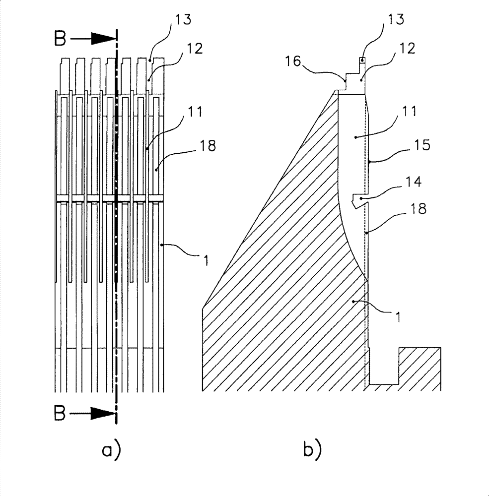
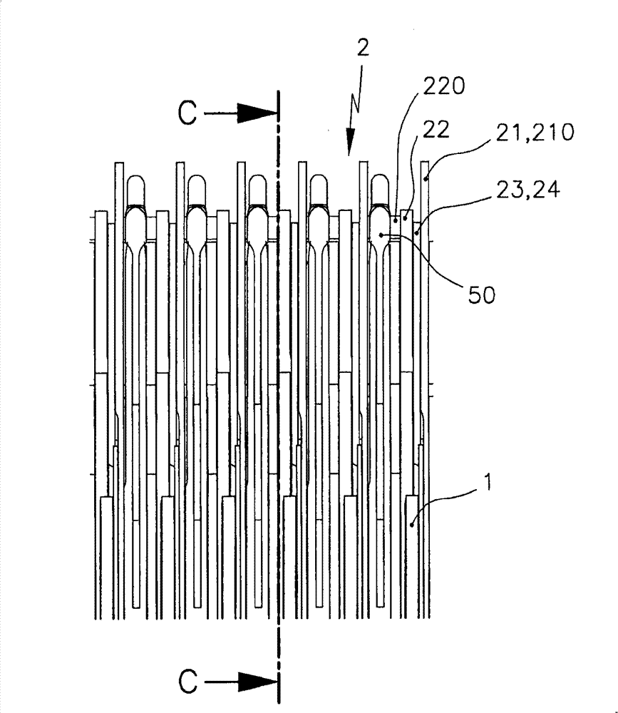
[0040] figure 2 a is a section of the loop forming area of ​​the needle bed 1 when the needle bed 1 is viewed from the top, in which the box 2 designed according to the first solution of the present invention is arranged, and the box 2 contains the components required for loop forming.

[0041] figure 2 b shows along figure 2 The area of ​​the needle bed 1 where the cassette 2 is placed, as shown by the section line B-B in a.

[0042] The needle bed 1 contains grooves 18 for accommodating needles 50 which, although only visible in the area shown, extend across the entire width of the needle bed perpendicular to the longitudinal sides of the needle bed outside the stitching area. The groove 11 is arranged parallel to the groove 18 in the region of the loop. Box 2 ( image 3 , Figure 4 ) is fixed in the slot 11 in the position of its associated needle 50 . The grooves 12 extending perpendicular to the plane of the needle bed, that is to say perpendicular to the plane i...


PUM


Abstract

The cartridge (2) has an active element required for knitting, where cartridge is fastened and / or detached to and from a needle bed (1') of a knitting machine without a tool. The active element comprises a knitting unit (210), protective edge (220), suppression element (23), and two side plates (21, 22). The knitting unit is formed at the plate (21) and the edge is formed at the plate (22). The suppression element is arranged between the plates which are connected by bolts (25, 26). A slider (24) movable into the cartridge is led through the bolts. An independent claim is also included for a knitting machine comprising a needle bed and a knitting tool.

Description

technical field [0001] The present invention relates to a cassette which can be fixed on a needle bed of a loom and a loom with such a cassette. Background technique [0002] With the advent of flat looms, there is a risk of damage to the loop-forming devices protruding outwards from the longitudinal sides of the needle bed close to the loops when the thread guides or the needles collide. The loop forming device is thus no longer milled into the longitudinal side of the needle bed adjacent to the stitches, but inserted as a separate component into the longitudinal side of the needle bed adjacent to the stitches. [0003] In the needle beds of the prior art, damaged parts in the looping area are replaceable. But the replacement process is not simple and takes a long time. [0004] figure 1 a is a top view of a cut-out portion of the loop-forming region of a needle bed 1" according to the prior art. [0005] figure 1 b is to press figure 1 Cross-sectional view of the 1" ...

Claims


Application Information

Patent Timeline
Patent Type & Authority Patents(China)
IPC IPC(8): D04B35/00D04B15/10D04B15/06D04B27/06D04B27/04
CPCD04B15/06D04B15/10
Inventor G・戈茨J・莫尔S・沃思S・迈耶M・塞德莱格
Owner KARL MAYER STOLL R&D GMBH
Why Eureka
Try Eureka