Booster type electric pressure-regulating valve

A pressure regulating valve and power-assisted technology, which is applied in the field of power-assisted electric pressure regulating valves, can solve the problems that the valve cannot be automatically controlled, opened without permission, cannot control the flow rate, and prevent the valve from opening without permission.

Inactive Publication Date: 2009-07-15
王宏林
View PDF1 Cites 3 Cited by
  • Summary
  • Abstract
  • Description
  • Claims
  • Application Information

AI Technical Summary

Problems solved by technology

[0002] In the water-saving automatic irrigation of farmland, the requirements for valves are getting higher and higher. Not only the valves are required to be automatically controlled, but also to prevent the valves from being opened privately. The fluid outlet extension body on the upper part of the valve body has pressure guiding holes connected with the fluid inlet and outlet respectively on the upper end surface of the valve body. On the contact surface of the body, there are pressure guide holes that match with the pressure guide holes on the valve body and communicate with the direction selection plug valve. A gate plate located on the upper part of the fluid outlet extension body is fixed on the valve body and the valve cover. Depending on the position of the plug valve, a pressure difference is formed on both sides of the gate to form the opening and closing of the valve, but the valve cannot be automatically controlled, nor can it control the flow rate and prevent the valve from opening without authorization.

Method used


Image

  • Booster type electric pressure-regulating valve
  • Booster type electric pressure-regulating valve
  • Booster type electric pressure-regulating valve

Examples


Embodiment 1

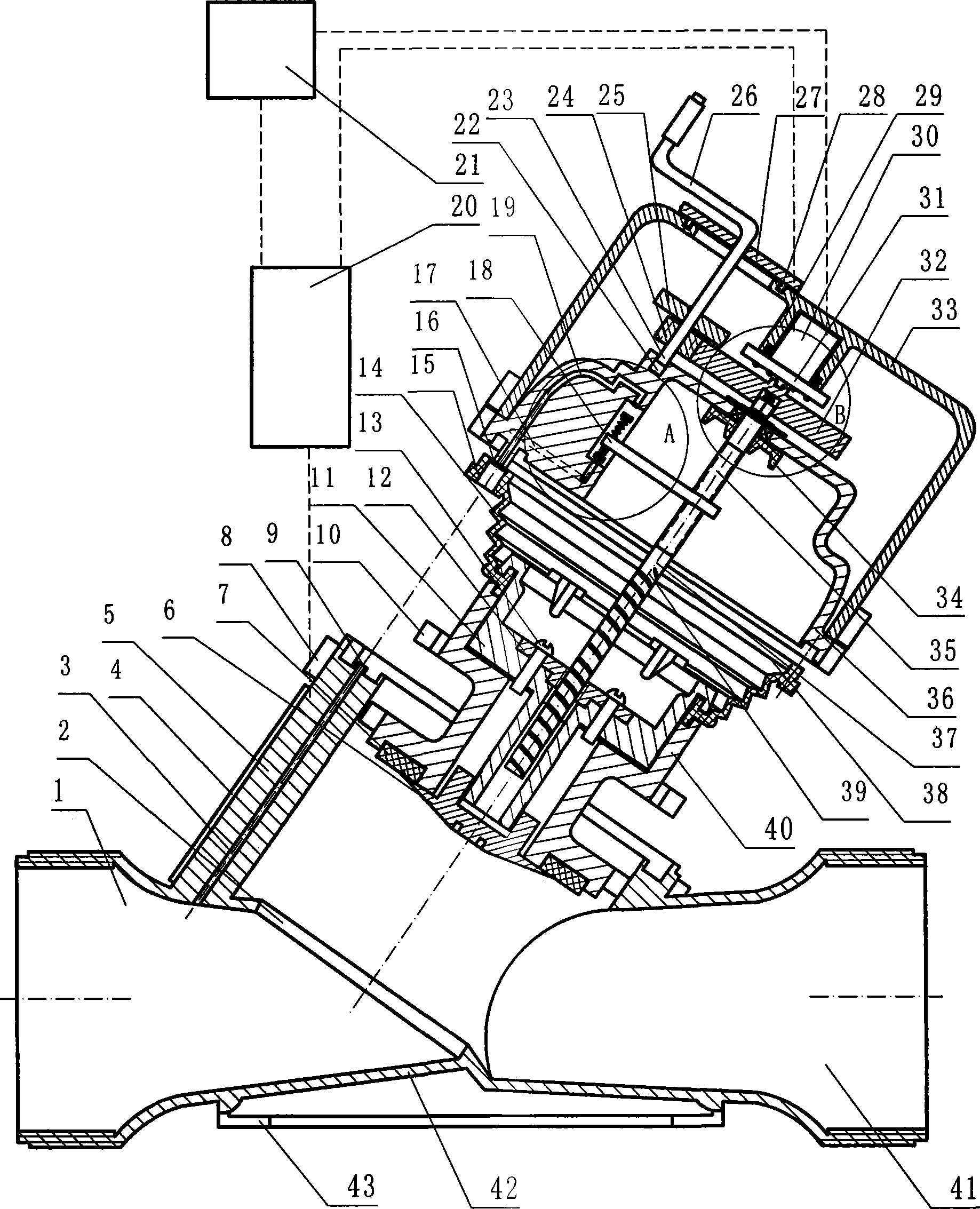
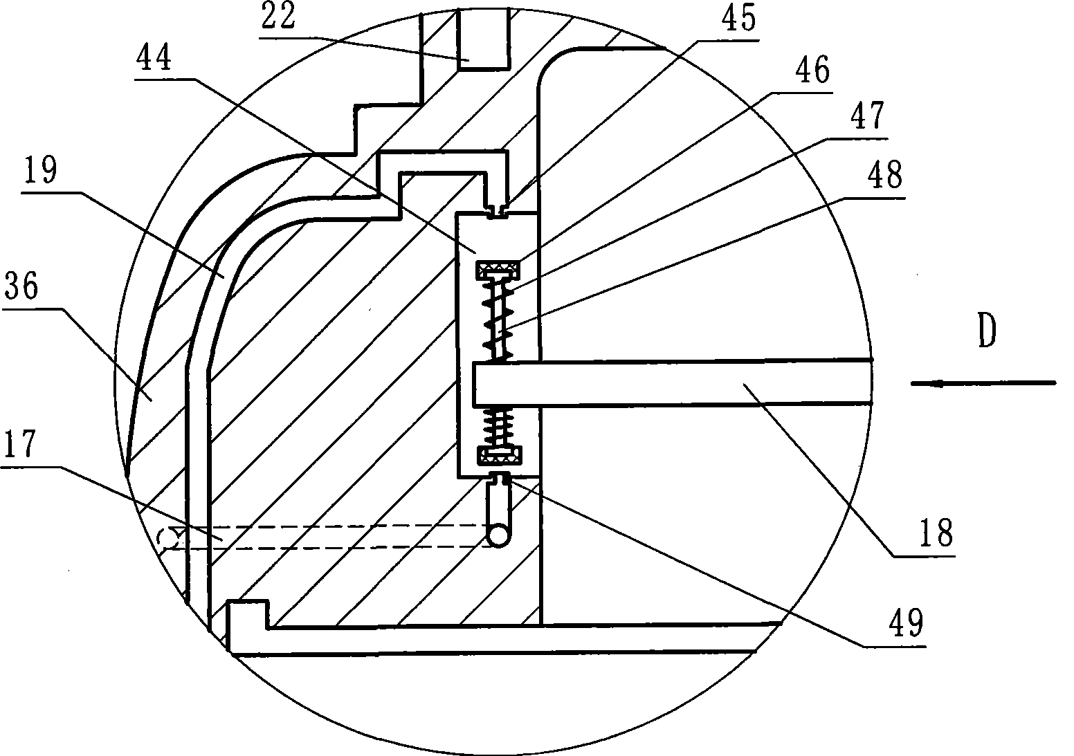
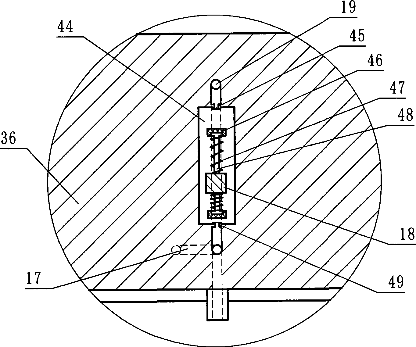
[0023] refer to figure 1 -5 is a schematic structural diagram of Embodiment 1 of the present invention, the valve body 42 is provided with an inclined valve seat 5, and the bottom of the valve seat 5 is the passage port 2, and the edge of the passage port 2 is slightly upwardly warped in order to make the sealing better From the beginning, the caliber of the passage port 2 is smaller than the inner diameter of the valve seat 5, and a guide tube 3 is provided on the side wall of the valve seat 5, and the guide tube 3 is connected to the water inlet of the valve body 42, and the outlet 9 of the guide tube is connected to A protruding nozzle is formed in the sealing groove at the upper end of the valve body 42 , and a lug seat 8 is also provided around the side wall at the top of the valve seat 5 for fixed connection with the lug seat on the valve cover 36 . A spool 40 is arranged in the valve seat 5, a valve plug 6 and a sealing ring 7 are arranged at the bottom of the spool 40,...

Embodiment 2

[0026] refer to Figure 6 , is a structural schematic diagram of Embodiment 2 of the present invention. The main difference between Embodiment 2 and Embodiment 1 is that the plunger heads 46 at both ends of the plunger 48 in Embodiment 2 are conical, and at the same time, the outlet nozzle 49 and the water inlet pipe Mouth 45 is provided with rubber pad 57, also can play same effect.

Embodiment 3

[0028] refer to Figure 7 , is a structural schematic diagram of Embodiment 3 of the present invention. The main difference between Embodiment 3 and Embodiment 1 is that: no screw cap 12 is provided in Embodiment 3, and the thick wire portion 39 of the lead screw 37 is directly screwed on the core seat 11. The same effect can also be achieved. In addition, Figure 6 Do not draw rocking handle 26 among, when not using rocking handle 26, seal cover 58 is covered on the hole on the motor chamber cover 33, prevents water or sundry from entering.


PUM


Abstract

The invention discloses a power-assisted electronic pressure regulating valve, comprising a valve body, a valve seat, a valve core and a valve cover; wherein the bottom part of the valve core is provided with a valve plug; the upper part of the valve core is provided with an annular cockle rubber cup; the side surface of the valve seat is provided with a draft tube which is connected with the water inlet of the valve and communicated with the inside of a seal cavity formed by the valve cover, the rubber cup and the valve core; an outflow tube is accessed to the outside of the valve body by the seal cavity; meanwhile, an electric or electromagnetic starting-closing device is arranged to control the on-off of the draft tube and the outflow tube, thereby controlling the on-off of the valve, solving the problems of automatically opening and closing the valve, and realizing automatic control with micro-power consumption; the zero-power consumption self-locking function of the valve at any opening angle reduces the water loss during an over-current, and solves the problems of automatically opening and closing the valve; moreover, the flux size can be controlled, and the valve can be prevented from being freely opened and closed. The power-assisted electronic pressure regulating valve has reasonable structure, is scientifically designed, is convenient for use, not only can be used on a water tube, but also can be suitable for other liquid or gases.

Description

Technical field: [0001] The invention relates to a valve, especially a power-assisted electric pressure regulating valve. Background technique: [0002] In the water-saving automatic irrigation of farmland, the requirements for valves are getting higher and higher. Not only the valves are required to be automatically controlled, but also to prevent the valves from being opened privately. The fluid outlet extension body on the upper part of the valve body has pressure guiding holes connected with the fluid inlet and outlet respectively on the upper end surface of the valve body. On the contact surface of the body, there are pressure guide holes that match with the pressure guide holes on the valve body and communicate with the direction selection plug valve. A gate plate located on the upper part of the fluid outlet extension body is fixed on the valve body and the valve cover. The difference in the position of the plug valve creates a pressure difference on both sides of th...

Claims


Application Information

Patent Timeline
Patent Type & Authority Applications(China)
IPC IPC(8): F16K31/14F16K1/04
Inventor 王宏林
Owner 王宏林
Why Eureka
Try Eureka