Booster type electric pressure-regulating valve
A pressure regulating valve and booster technology, applied in the field of booster electric pressure regulating valve, can solve the problems of private opening, the valve cannot be automatically controlled, the flow rate cannot be controlled, and the valve can not be opened privately, so as to reduce water loss and have a reasonable structure. , the effect of design science
- Summary
- Abstract
- Description
- Claims
- Application Information
AI Technical Summary
Problems solved by technology
Method used
Image
Examples
Embodiment 1
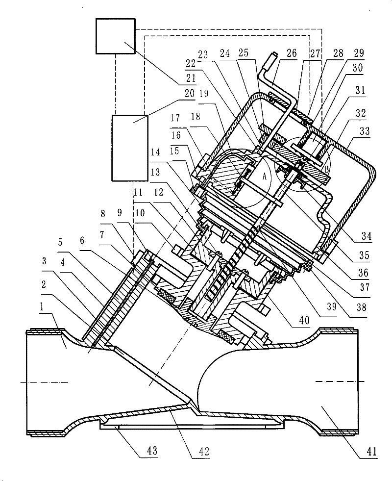
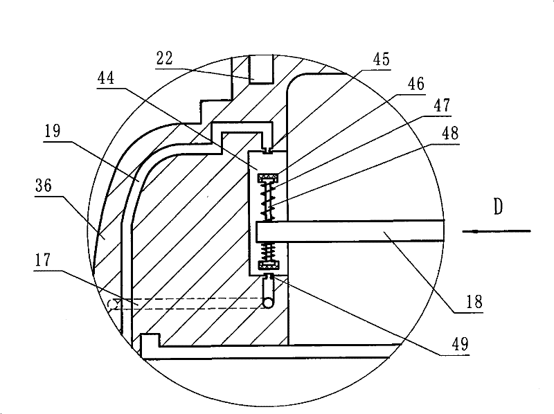
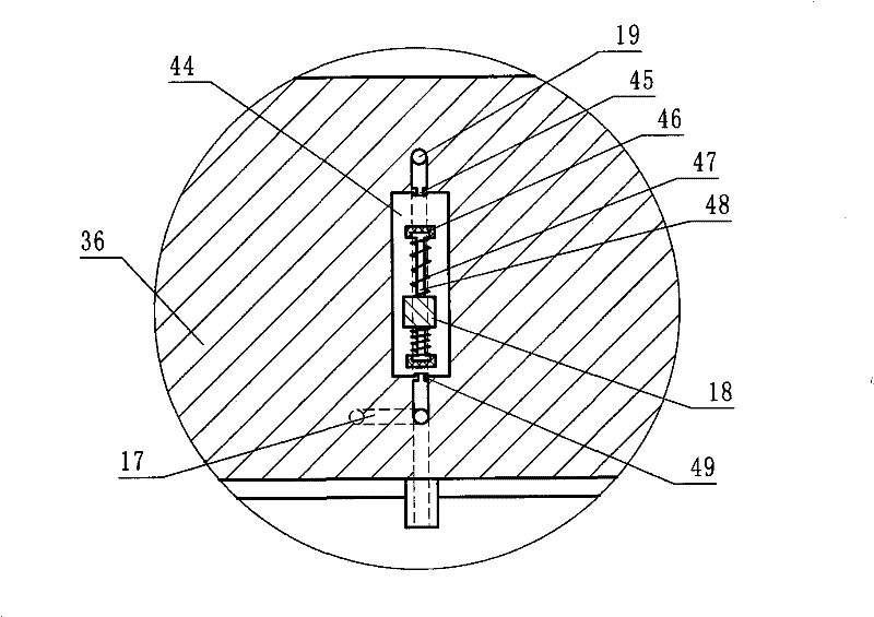
[0023] refer to figure 1 -5 is a schematic structural diagram of Embodiment 1 of the present invention, the valve body 42 is provided with an inclined valve seat 5, and the bottom of the valve seat 5 is the passage port 2, and the edge of the passage port 2 is slightly upwardly warped in order to make the sealing better From the beginning, the caliber of the passage port 2 is smaller than the inner diameter of the valve seat 5, and a guide tube 3 is provided on the side wall of the valve seat 5, and the guide tube 3 is connected to the water inlet of the valve body 42, and the outlet 9 of the guide tube is connected to A protruding nozzle is formed in the sealing groove at the upper end of the valve body 42 , and a lug seat 8 is also provided around the side wall at the top of the valve seat 5 for fixed connection with the lug seat on the valve cover 36 . A spool 40 is arranged in the valve seat 5, a valve plug 6 and a sealing ring 7 are arranged at the bottom of the spool 40,...
Embodiment 2
[0026] refer to Figure 6 , is a structural schematic diagram of Embodiment 2 of the present invention. The main difference between Embodiment 2 and Embodiment 1 is that the plunger heads 46 at both ends of the plunger 48 in Embodiment 2 are conical, and at the same time, the outlet nozzle 49 and the water inlet pipe Mouth 45 is provided with rubber pad 57, also can play same effect.
Embodiment 3
[0028] refer to Figure 7 , is a structural schematic diagram of Embodiment 3 of the present invention. The main difference between Embodiment 3 and Embodiment 1 is that: no screw cap 12 is provided in Embodiment 3, and the thick wire portion 39 of the lead screw 37 is directly screwed on the core seat 11. The same effect can also be achieved. In addition, Figure 6 Do not draw rocking handle 26 among, when not using rocking handle 26, seal cover 58 is covered on the hole on the motor chamber cover 33, prevents water or sundry from entering.
PUM
 Abstract
Description
Claims
Application Information
 - R&D
- Intellectual Property
- Life Sciences
- Materials
- Tech Scout
- Unparalleled Data Quality
- Higher Quality Content
- 60% Fewer Hallucinations
Browse by: Latest US Patents, China's latest patents, Technical Efficacy Thesaurus, Application Domain, Technology Topic, Popular Technical Reports.
© 2025 PatSnap. All rights reserved.Legal|Privacy policy|Modern Slavery Act Transparency Statement|Sitemap|About US| Contact US: help@patsnap.com


