A clinical auxiliary retention device for medical intensive care medicine

A clinical and medical technology, which is applied in the field of clinical auxiliary retention devices for critical care medicine, can solve the problems of insufficient comfort and inability to adjust the fixed position, etc., and achieve the effect of convenient nursing

Active Publication Date: 2022-04-22
霍华淞
View PDF15 Cites 0 Cited by
  • Summary
  • Abstract
  • Description
  • Claims
  • Application Information

AI Technical Summary

Problems solved by technology

[0005] The above-mentioned auxiliary fixing device is clamped on the side of the bed, and the patient needs to stretch the legs to the side of the bed when fixing the patient's legs, so that the fixing is not only not comfortable enough, but also the fixing position cannot be adjusted;

Method used


Image

  • A clinical auxiliary retention device for medical intensive care medicine
  • A clinical auxiliary retention device for medical intensive care medicine
  • A clinical auxiliary retention device for medical intensive care medicine

Examples


Embodiment 1

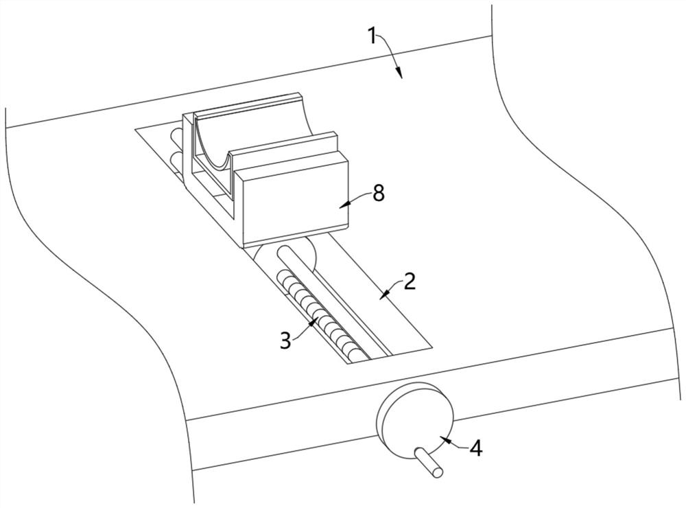
[0054] see figure 1 and figure 2 , a clinical auxiliary retention device for critical care medicine, comprising a nursing bed 1, a horizontal groove 2 is opened on the nursing bed 1, a screw rod 3 is installed in the inner rotation of the horizontal groove 2, and one end of the screw rod 3 is rotated and arranged on the horizontal On the inner wall of the groove 2, the other end of the screw rod 3 extends to the outside of the nursing bed 1 and is fixedly connected with a handle 4, through which the rotation of the screw rod 3 is conveniently controlled;

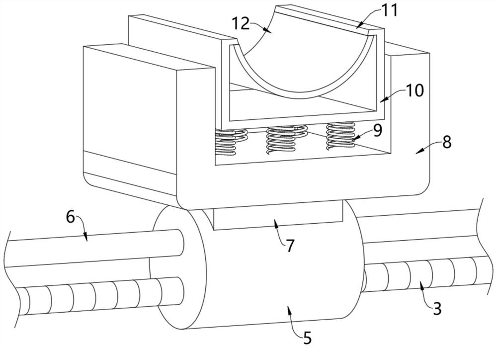
[0055] The outer wall of the screw rod 3 is threadedly connected with a screw nut 5, and the inside of the screw nut 5 is plugged with a limit rod 6. The insertion inside limits the rotation of the screw nut 5, so that the screw nut 5 can only do left and right translational movement driven by the screw rod 3;

[0056] The top of the screw nut 5 is fixedly installed with a connecting plate 7, and the top of the connecting...

Embodiment 2

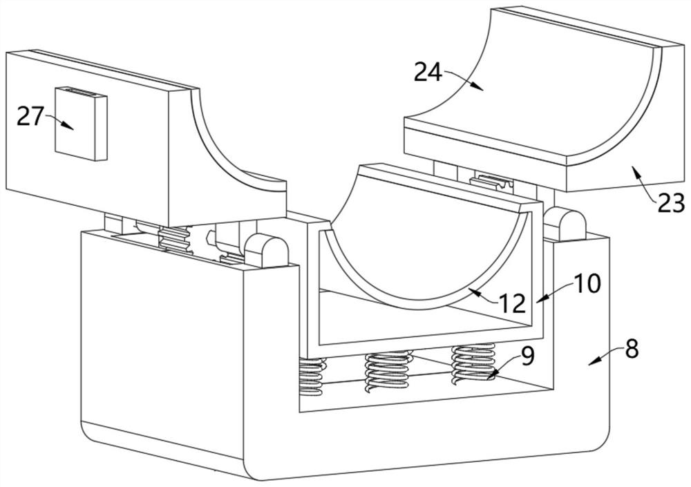
[0060] see Figure 3-Figure 5 , on the basis of Embodiment 1, side cavities 14 are opened on the opposite sides of the two side plates, driving wheels 15 are rotated inside the two side cavities 14, and the outer walls of the left and right sides of the U-shaped frame 10 are provided with Teeth 13 are provided, and the teeth 13 on the outer walls of the left and right sides of the U-shaped frame 10 mesh with two driving wheels 15 respectively, and the tops of the two driving wheels 15 are meshed with intermediate wheels 17, and the tops of the two intermediate wheels 17 Both drive wheels 19 are meshed, and a third rotating shaft 20 is fixedly installed at the center of the two driving wheels 19. Both ends of the two third rotating shafts 20 are rotatably connected with a positioning seat 21, and the positioning seat 21 is fixedly installed on the side. On the top of the plate, the outer walls of the two third rotating shafts 20 are fixed with fixed plates 22, and the tops of t...

Embodiment 3

[0067] see Figure 6-Figure 8 , on the basis of Embodiment 1 and Embodiment 2, the bottoms of the two rotating blocks 23 are fixedly equipped with a medicine box 28, and an inner cavity 29 is formed inside the two rotating blocks 23, and the inside of the inner cavity 29 is filled with The sponge 30, the inner chamber 29 and the medicine box 28 are connected through the connecting pipe 31, the inner wall of the arc-shaped groove is uniformly provided with a medicine groove 33, and the inside of the arc-shaped pressure pad 24 is evenly provided with a medicine outlet hole;

[0068] When the rotating block 23 was in the initial position, the connecting pipe 31 was positioned at the top of the medicine box 28. At this time, the medicinal liquid in the medicine box 28 was stored in the medicine box 28 and could not be discharged; 31 is located on the side of the medicine box 28 and is arranged horizontally with the medicine box 28. At this time, the medicine solution in the medici...


PUM


Abstract

The present invention relates to the technical field of medical auxiliary equipment, and discloses an auxiliary retention device for clinical use in critical care medicine, including a nursing bed, a horizontal groove is opened on the nursing bed, and a screw rod is arranged inside the horizontal groove. The outer wall of the screw rod is threadedly connected with a screw nut, and the inside of the screw nut is plugged with a limit rod, and both ends of the limit rod are fixedly installed on the inner wall of the transverse groove; the screw rod can be rotated by turning the handle , the rotation of the screw rod drives the screw nut connected by the thread on the outer wall to move left and right, and the left and right movement of the screw nut can drive the U-shaped frame to move left and right through the connecting plate, and adjust the left and right positions of the U-shaped frame, that is, adjust the fixed position of the patient's legs. It is more convenient, and the position of the auxiliary retention device can be adjusted according to the actual situation of the patient, so that the patient's legs are more comfortable during fixation; the invention has a novel design and has the advantage of being convenient for adjusting the fixation position.

Description

technical field [0001] The invention relates to the technical field of medical auxiliary devices, in particular to an auxiliary retention device for clinical use in intensive care medicine. Background technique [0002] In clinical nursing, limb immobilization devices are often used. Limb immobilization devices can provide positioning and support for the patient's limbs, limit the patient's limb activities, and make it easier for medical staff to care for the patient's limbs; among the limb immobilization devices, the most common , The most commonly used leg fixation device, when nursing the injured leg, it is necessary to use the leg fixation device to fix the leg to speed up the recovery of leg injuries, especially for leg trauma For critically ill patients, it is necessary to provide effective support and fixation to ensure the healing of the trauma; [0003] The Chinese patent announcement number is: CN113018050A invention patent, which provides an auxiliary fixing devi...

Claims


Application Information

Patent Timeline
Patent Type & Authority Patents(China)
IPC IPC(8): A61G7/05A61G7/075A61B90/14A61H33/06A61M37/00
CPCA61G7/05A61G7/0755A61B90/14A61H33/06A61M37/00A61M2037/0007A61H2033/061A61H2033/068A61H2201/0207A61H2201/105A61H2205/10
Inventor 霍华淞沈姝睿
Owner 霍华淞
Why Eureka
Try Eureka