Hydraulic coupling with freely regulated coupling direction

A hydraulic pipe joint, axial technology, applied in the direction of adjustable connections, pipes/pipe joints/fittings, passing elements, etc., to avoid twisting of hoses or too small bending radius, and to achieve the effect of easy docking

Inactive Publication Date: 2009-07-15
CHINA NON-FERROUS METALS PROCESSING TECH CO LTD
View PDF0 Cites 7 Cited by
  • Summary
  • Abstract
  • Description
  • Claims
  • Application Information

AI Technical Summary

Problems solved by technology

[0003] The technical problem to be solved by the present invention is to provide a new type of hydraulic pipe joint. This pipe joint can adjust the connection direction arbitrarily, making it easier to connect with metal pipes or hydraulic hoses, and can conveniently realize reasonable bending of the hose, avoiding twisting of the hose. Problems such as too small bending radius

Method used


Image

  • Hydraulic coupling with freely regulated coupling direction
  • Hydraulic coupling with freely regulated coupling direction
  • Hydraulic coupling with freely regulated coupling direction

Examples


Embodiment Construction

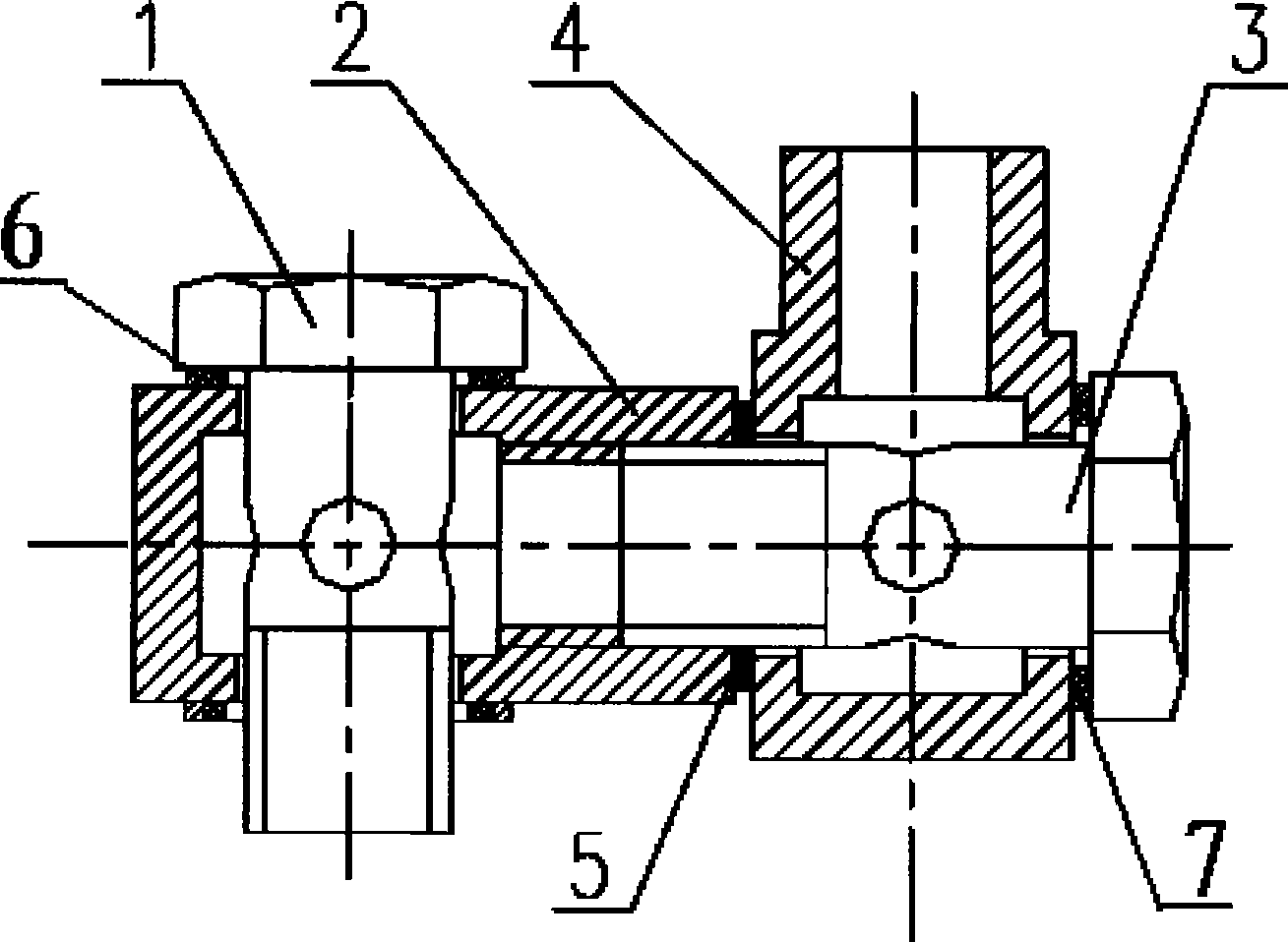
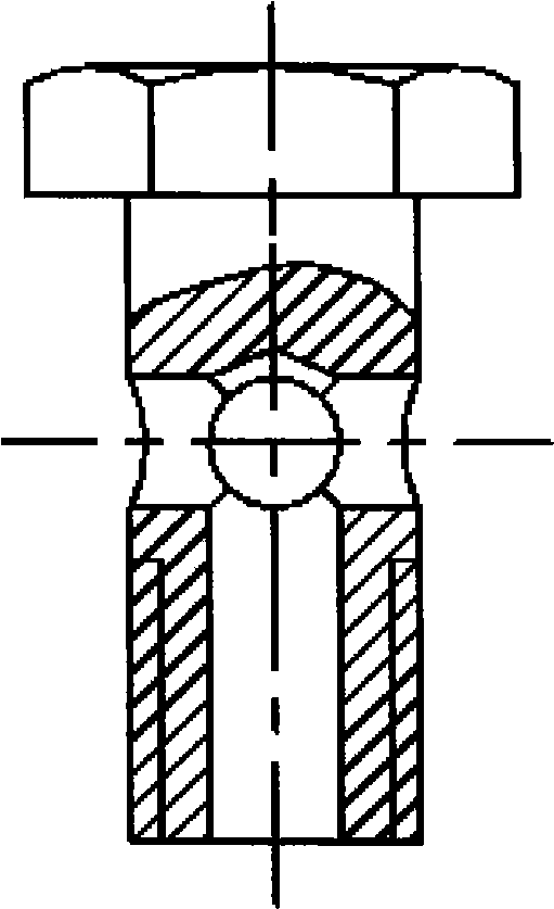
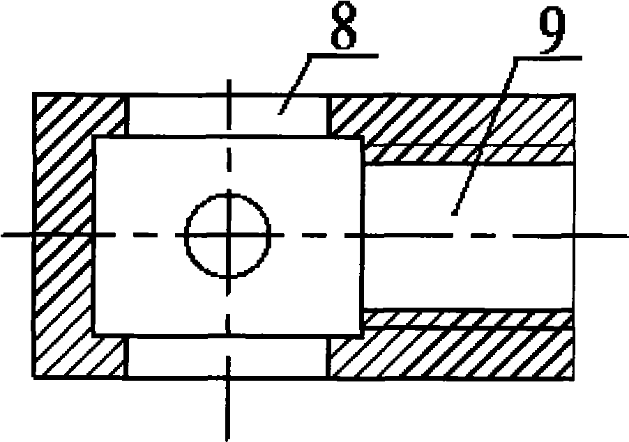
[0010] like figure 1 As shown, a hydraulic pipe joint of the present invention that can adjust the connection direction arbitrarily consists of a hollow bolt 1, a rotary body 2, a hollow bolt 2 3, a rotary body 4, and several combined sealing washers 5, 6, 7, etc. composition. like figure 2 As shown, the hollow bolt 1 has fluid passages both axially and radially. like image 3 As shown, the rotary body-2 is processed with a through hole 8, and there is a connecting oil port 9 in the radial direction, and there is a thread in the oil port. The structure of the hollow bolt two 3 is basically the same as that of the hollow bolt one 1, and the structures of the second rotator 4 and the first 2 of gyratory are also similar. The external thread of the hollow bolt two is matched with the internal thread of the rotary body one connecting the oil port 9. The first rotary body can rotate 360 ​​degrees around the hollow bolt one, and the second rotary body can rotate 360 ​​degrees ...


PUM


Abstract

The invention discloses a hydraulic pipe joint capable of freely adjusting connecting directions. The joint comprises two sets of hollow bolts, two revolving bodies and a plurality of combined seal rings. The coaxial direction and the radial direction of the hollow bolts are all provided with an oil path channel; the revolving bodies are provided with a through hole along the direction of a rotating shaft; the vertical direction is provided with a bypass hydraulic fluid port with an inner thread; the hollow bolts penetrate from the through hole; the two ends of the through hole are sealed by a combined seal gasket; the hollow bolts, the revolving bodies and the combined seal gasket form a hinged joint; the revolving bodies can revolve along the hollow bolts by 360 degrees; and the outer thread of the hollow bolt II is connected with the inner thread of the revolving body I. As the revolving body I can revolve by 360 degrees and the revolving body II can revolve by 360 degrees opposite to the revolving body I, the hydraulic fluid port of the revolving body II can be led to face to any direction by adjusting the revolving corners of the two revolving bodies; therefore, the hydraulic pipe joint is very easy to be jointed with a metal pipe or a hydraulic hose, thus being capable of achieving the goals of optimizing the direction of the metal pipe and leading the hydraulic hose to be reasonably bent.

Description

technical field [0001] The invention relates to a hydraulic pipeline system, in particular to a hydraulic pipe joint whose connection direction can be adjusted arbitrarily. Background technique [0002] A variety of pipe joints are often used in hydraulic piping systems, among which there are rotary joints and welded articulated pipe joints that can adjust the direction. These two joints can only adjust the direction in the two-dimensional plane, and cannot The direction can be adjusted arbitrarily in the space. Therefore, under some special space conditions, when these pipe joints are used to connect metal pipes or hydraulic hoses, it will cause difficulties in docking, especially for hydraulic hoses, and sometimes it is easy to cause the hose to twist or bend. The radius is too small, which will affect the service life of the hose. Contents of the invention [0003] The technical problem to be solved by the present invention is to provide a new type of hydraulic pipe jo...

Claims


Application Information

Patent Timeline
Patent Type & Authority Applications(China)
IPC IPC(8): F16L27/093
Inventor 段宏波
Owner CHINA NON-FERROUS METALS PROCESSING TECH CO LTD
Why Eureka
Try Eureka