Turbine and method for detecting rubbing

a technology of turbines and rotors, applied in the field of turbines, can solve the problems of only allowing basic detection of rubbing, and achieve the effects of optimizing the minimization of the gap between the rotors, increasing output, and optimizing the efficiency of the turbin

Inactive Publication Date: 2016-05-19
SIEMENS AG
View PDF1 Cites 0 Cited by
  • Summary
  • Abstract
  • Description
  • Claims
  • Application Information

AI Technical Summary

Benefits of technology

[0019]The advantages achieved by the invention consist in particular in the fact that, as a result of the exactly localizable detection of contact between rotor and housing, still further optimized minimization of the gaps between rotor and housing is made possible by technically particularly simple means. Rubbing can be detected at many locations both in the axial and in the circumferential direction during the operation of the

Problems solved by technology

In order to achieve a high efficiency, the gap between blade end and housing should be a minimum, however, since fluid flows past the rotor blades

Method used


Image

  • Turbine and method for detecting rubbing
  • Turbine and method for detecting rubbing
  • Turbine and method for detecting rubbing

Examples


Embodiment Construction

[0025]The same parts are provided with the same designations in all the figures.

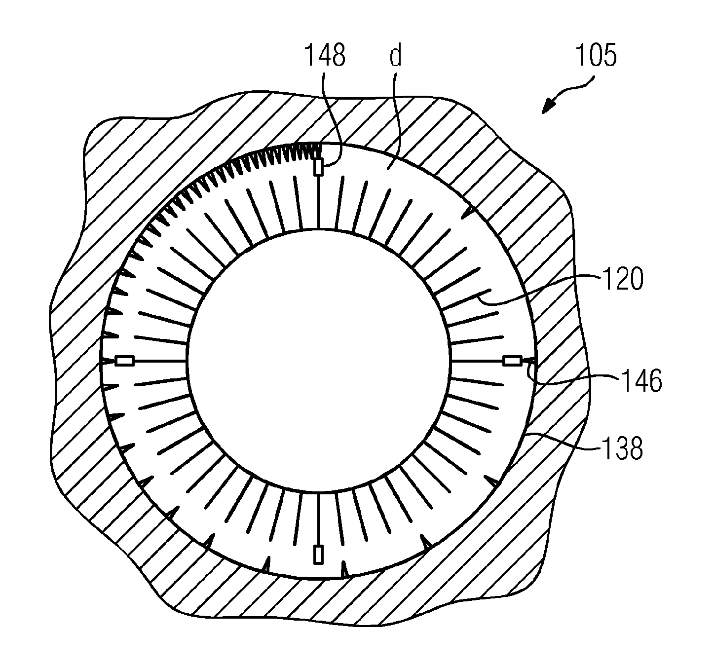
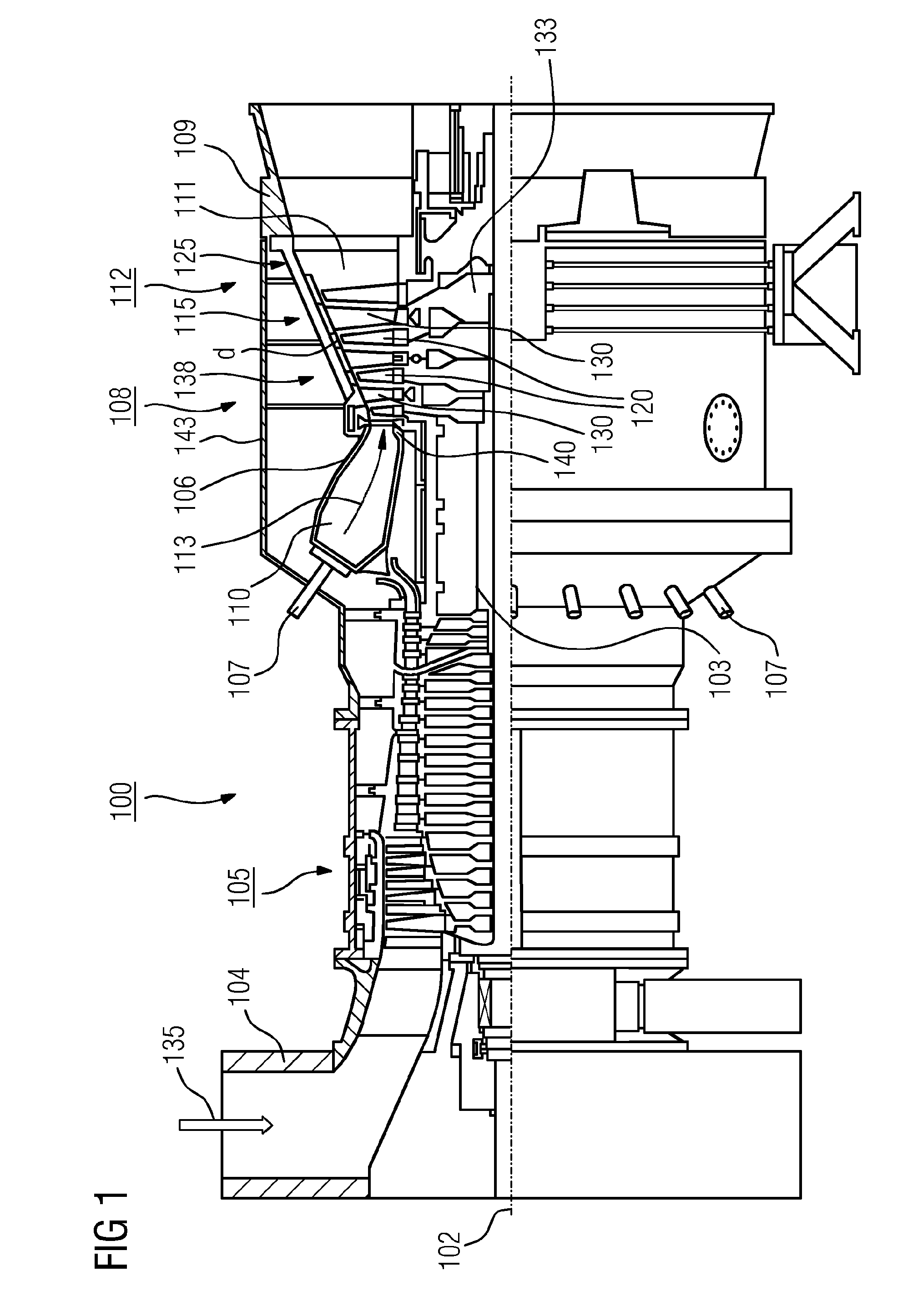
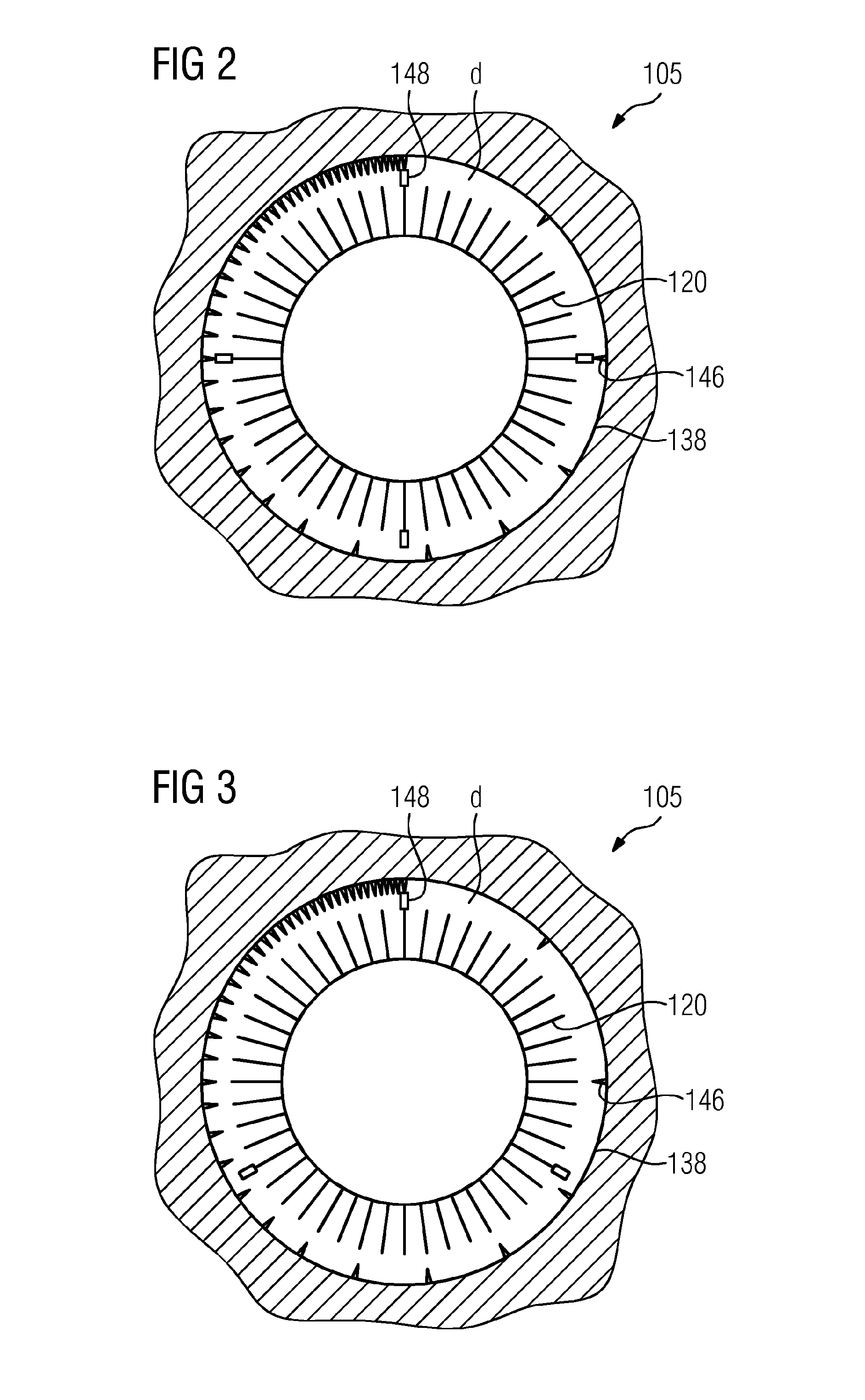
[0026]FIG. 1 shows a turbine 100, here a gas turbine, in a partial longitudinal section. The gas turbine 100 has in the interior a rotor 103, which is also designated a turbine rotor, mounted such that it can rotate about an axis of rotation 102 (axial direction). Along the rotor 103, an intake housing 104, a compressor 105, a toroidal combustion chamber 110, in particular an annular combustion chamber 106, having a plurality of burners 107 arranged coaxially, a turbine 108 and the exhaust gas housing 109 follow one another.

[0027]The annular combustion chamber 106 communicates with an annular hot gas channel 111. There, for example, four turbine stages 112 connected one behind another form the turbine 108. Each turbine stage 112 is formed from two rings of blades. As seen in the flow direction of a working medium 113, a row 125 formed from rotor blades 120 follows in the hot gas channel 111 of a row 115 ...


PUM


Abstract

A turbine, in particular a gas turbine, includes a rotor, a housing spaced from the rotor by a gap, and a system for monitoring structure-borne noise, permit rubbing of the rotor and the housing to be localised with the least possible technical complexity. In both a first and second axial region, one or more inwardly directed rubbing teeth of the housing and one or more outwardly directed rubbing edges of the rotor are arranged, wherein the one or more rubbing teeth and the one or more rubbing edges are distributed along the circumference such that contact of the particular rubbing teeth and rubbing edges at a specified rotational frequency of the rotor occurs at a different frequency in the first axial region than in the second axial region.

Description

CROSS REFERENCE TO RELATED APPLICATIONS[0001]This application is the U.S. National Stage of International Application No. PCT / EP2014 / 062787 filed Jun. 18, 2014, and claims the benefit thereof. The International Application claims the benefit of German Application No. DE 102013212252.7 filed Jun. 26, 2013. All of the applications are incorporated by reference herein in their entirety.FIELD OF INVENTION[0002]The invention relates to a turbine, in particular a gas turbine, comprising a rotor, a housing spaced apart from the rotor by a gap, and a system for monitoring structure-borne noise. It further relates to a method for detecting rubbing in a turbine, in particular a gas turbine, comprising a rotor, a housing spaced apart from the rotor by a gap, and a system for monitoring structure-borne noise.BACKGROUND OF INVENTION[0003]A turbine is a fluid-flow machine which converts the internal energy (enthalpy) of a flowing fluid (liquid or gas) into rotational energy and ultimately into me...

Claims


Application Information

Patent Timeline
IPC IPC(8): F01D21/00F01D25/24F01D5/02
CPCF01D21/003F01D5/02F05D2260/83F05D2220/32F05D2240/24F01D25/24F01D11/22F01D21/04
Inventor SEROKA, ALEXANDERCOSTAMAGNA, RAOULSIEBER, UWE
Owner SIEMENS AG
Why Eureka
Try Eureka