Duplex head milling machine for processing sole mould chamfering

A double-head milling machine and shoe sole mold technology, applied in the field of machinery, can solve the problems of low chamfering accuracy, low work efficiency, inconvenient processing, etc., and achieve the effects of high chamfering accuracy and improving work efficiency.

Active Publication Date: 2009-07-22
邵春华
View PDF9 Cites 11 Cited by
  • Summary
  • Abstract
  • Description
  • Claims
  • Application Information

AI Technical Summary

Problems solved by technology

Although the chamfer can be processed in this way, due to the structural limitation of the planer itself, it cannot be processed at one time during the processing of the chamfer. Only a very shallow chamfer can be planed each time. Chamfer with sufficient depth
Moreover, after each processing is completed, only one chamfer on the upper template or the lower template can be processed, and the mold itself needs 4 chamfers, so it needs to be repeated 4 times to process

Method used


Image

  • Duplex head milling machine for processing sole mould chamfering
  • Duplex head milling machine for processing sole mould chamfering
  • Duplex head milling machine for processing sole mould chamfering

Examples


Embodiment 1

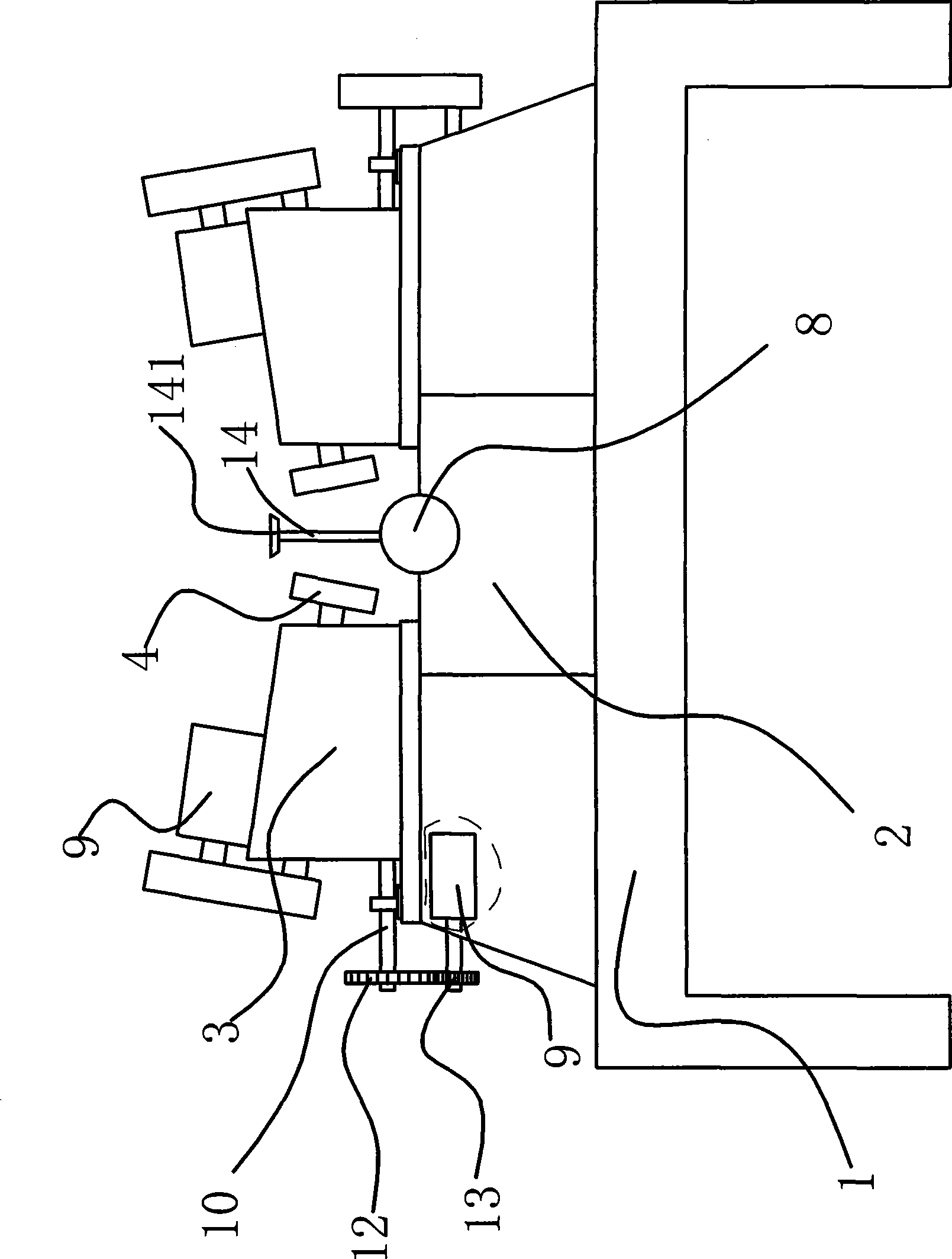
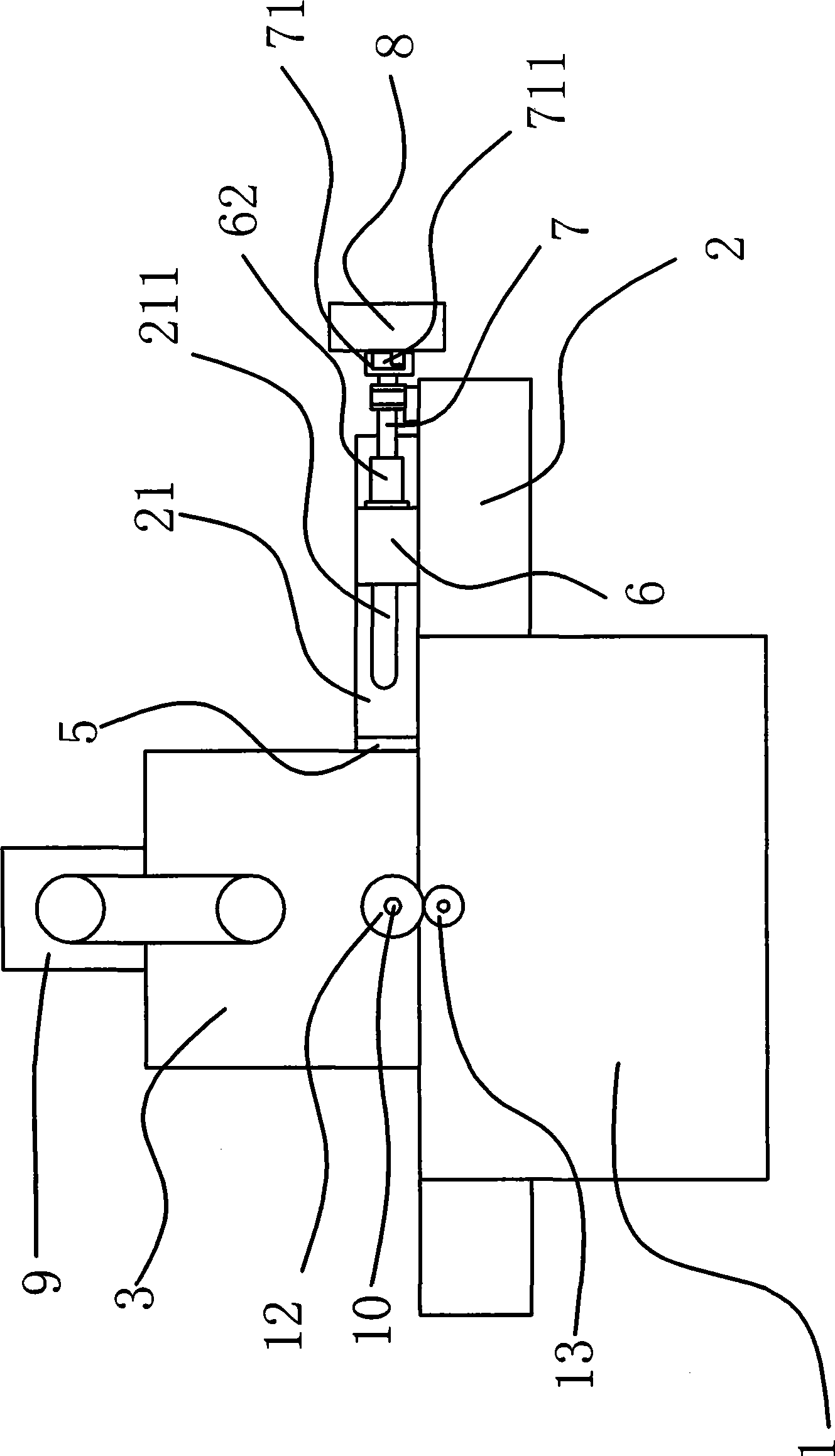
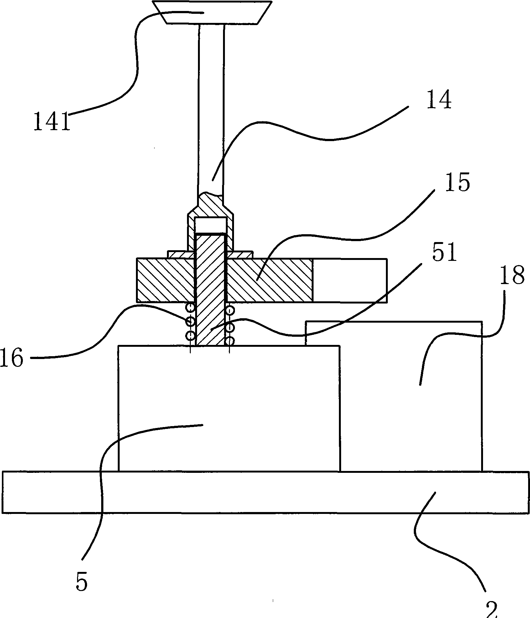
[0039] Such as figure 1 , figure 2 and Figure 4As shown, the double-headed milling machine used to process the chamfering of the sole mold includes a frame 1 and a workbench 2 that can move back and forth on the frame 1, and the workbench 2 is provided with a clamping device for clamping the mold 18. Two sets of milling units are symmetrically distributed on both sides of the clamping device, and the milling units on both sides of the workbench 2 are arranged in one-to-one correspondence. Each milling unit includes a machine base 3 and a milling cutter 4 obliquely arranged on the machine base 3 And the power mechanism for driving the milling cutter 4 to rotate is provided with an adjusting device capable of adjusting the distance between two opposite supports 3 between each support 3 and the frame 1 . The milling cutter 4 is obliquely arranged on the support 3 and can better process the chamfering of the sole mold 18 to make it more accurate.

[0040] Such as figure 1 an...

Embodiment 2

[0047] The content of embodiment 2 is basically the same as embodiment 1, and the difference is that the drive mechanism is a motor one and a nut seat 62 fixedly connected to the positioning part two 6, and the motor one is fixed on the workbench 2 and the motor one rotating shaft and the nut seat 62 connected. In this way, the second positioning piece 6 can also be driven to make the slider 61 of the second positioning piece slide in the bar-shaped opening 211 on the baffle plate 21 .

Embodiment 3

[0049] The content of embodiment 2 is basically the same as that of embodiment 1, the difference is that the driving mechanism is an air cylinder, the air cylinder is fixed on the workbench 2 and the main shaft of the air cylinder is connected with the positioning member 2 6 . This can also drive the second positioning piece 6 to make the slider 61 of the second positioning piece 6 slide in the bar-shaped opening 211 on the baffle plate 21 .


PUM


Abstract

The invention provides a duplex head milling machine for machining chamfer angle of sole mould and belongs to the technical field of machinery. The duplex head milling machine solves the problems that the prior squaring machine for machining mould wastes time and energy and has low working efficiency, and the machined chamfer angle has low precision. The duplex head milling machine for machining the chamfer angle of the sole mould comprises a frame and a worktable capable of moving on the frame; the worktable is provided with a clamping device for clamping the mould; two sides of the clamping device are provided with at least one set of a milling unit respectively; the milling units of two sides of the worktable are correspondingly arranged; each milling unit comprises a stand, a milling cutter arranged on the stand and a power mechanism 1 driving the milling cutter to rotate; and an adjusting device for adjusting distance between two relative stands is arranged between each stand and each frame. The duplex head milling machine has the advantages of high working efficiency, high precision of machining the chamfer angle, wide application range, and the like.

Description

technical field [0001] The invention belongs to the technical field of machinery, and relates to a milling machine, in particular to a double-head milling machine for processing the chamfering of shoe sole molds. Background technique [0002] The existing sole mold is composed of upper and lower templates, wherein there are chamfers on both sides of the outer surface edges of the upper and lower templates, so that when the sole mold is cast, the upper and lower templates are clamped by the mold base. Chamfering on both sides of the edge of the outer surface of the template, so as to clamp the upper and lower templates so that the upper and lower templates can be tightly attached together. [0003] When the upper and lower templates are just processed, their outer surfaces are smooth without chamfers. In order to process the chamfers of the upper and lower templates, people place the upper and lower templates on the planer, and use the planer The outer surface edges of the u...

Claims


Application Information

Patent Timeline
IPC IPC(8): B23C3/20
Inventor 邵春华
Owner 邵春华
Why Eureka
Try Eureka