Switch electric power apparatus

A switching power supply, switching tube technology, applied in emergency protection circuit devices, output power conversion devices, electrical components and other directions, can solve the problems of poor circuit stability, complex circuits, and high costs

Inactive Publication Date: 2009-07-22
叶建国
View PDF0 Cites 13 Cited by
  • Summary
  • Abstract
  • Description
  • Claims
  • Application Information

AI Technical Summary

Problems solved by technology

[0002] In switching power supply technology, the commonly used circuits are: forward (forward) type, flyback (flyback) type, half-bridge circuit, full-bridge circuit and push-pull circuit, etc.; the efficiency of the power supply structure mentioned above is 90 % or less; for loads that require high-voltage starting (ignition), such as gas discharge lamps: fluorescent lamps, low-pressure sodium lamps, high-pressure sodium lamps, and metal halide lamps, it is necessary to add additional starting circuits, such as lighting fluorescent lamps. Capacitor series resonant circuit generates high voltage to ignite fluorescent lamps. Low-pressure sodium lamps, high-pressure sodium lamps, metal halide lamps, etc. generally use full-bridge or half-bridge plus high-voltage triggers to start the ignition circuit. These circuits are not very complicated and the cost is extremely high, but the circuit stability is extremely poor , short life, especially easy to burn (such as commercially available energy-saving lamps)

Method used


Image

  • Switch electric power apparatus
  • Switch electric power apparatus
  • Switch electric power apparatus

Examples


Embodiment Construction

[0020] The present invention will be described in detail below in conjunction with the accompanying drawings and specific embodiments. The following description will help those skilled in the art better understand other advantages, objectives and features of the present invention.

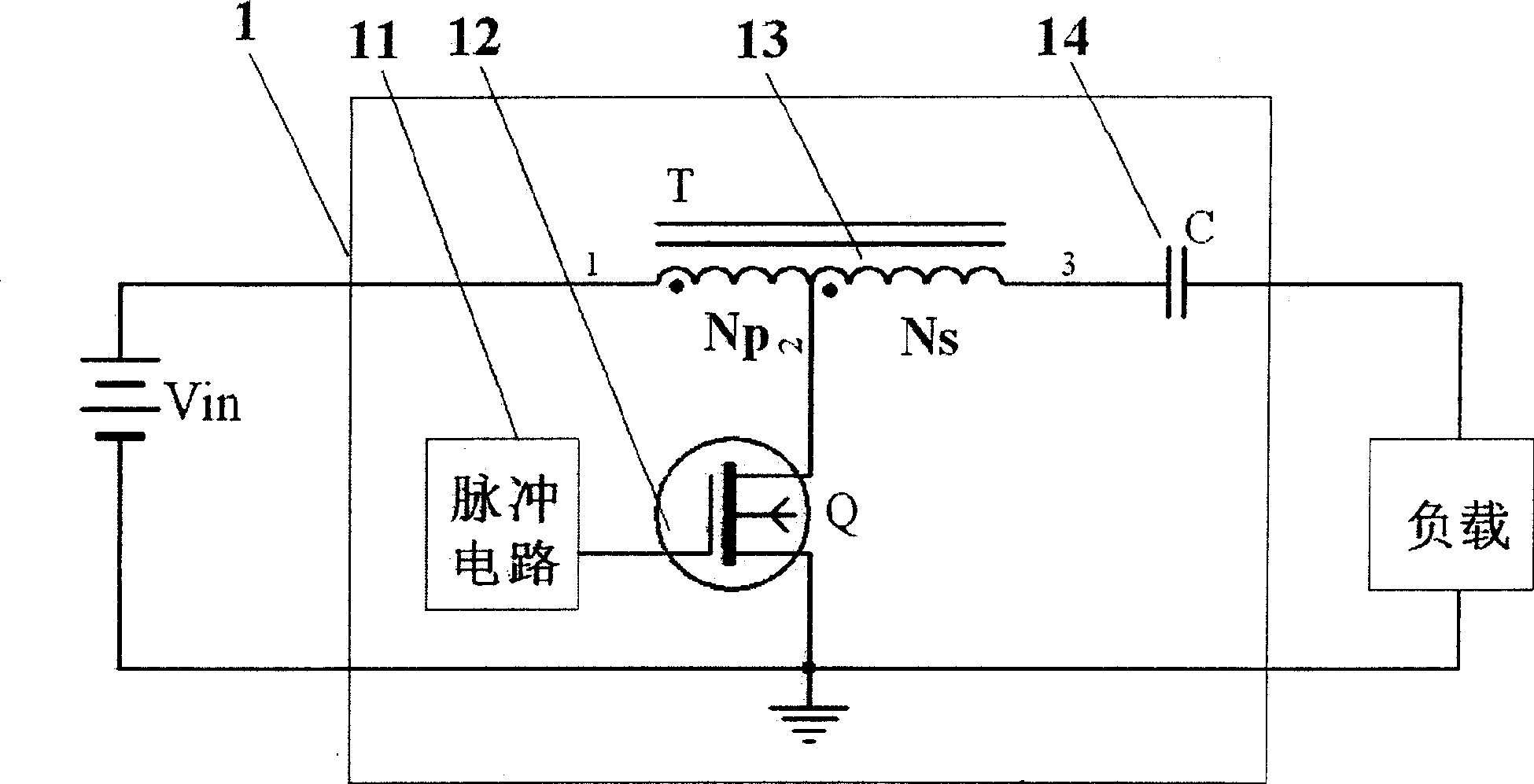
[0021] At first introduce the first embodiment of the device of the present invention, refer to figure 1 . figure 1 The switching power supply device 1 shown is used to drive the load with high-frequency AC, and the high-frequency AC driving process uses a resonant circuit; the device 1 mainly includes: a transformer 13, a capacitor 14, a switch tube 12, and a pulse circuit 11. In this way, in the switching power supply device 1, under the action of the pulse circuit 11, the switch tube 12 performs on and off actions (that is, the switch tube is turned on and off). When the switch tube 12 is turned on, the The primary side of the transformer 13 is connected to the input DC power supply, and at th...


PUM


Abstract

The invention discloses a technical proposal of a switch power supply device. The device is based on a resonance circuit. The device simultaneously uses a consequent mode and a retrace scanning mode and also the resonance circuit so as to generate a high frequency alternating current power supply for driving load. The device comprises a transformer, a switching tube, a capacitor, a pulse circuit and the like; wherein in the breakover stage of the switching tube, an input power supply outputs energy to the load by the transformer and the capacitor, and simultaneously the input power supply stores the energy in the transformer; in the stopping stage of the switching tube, the energy stored in the transformer is output to the load by the capacitor.

Description

technical field [0001] The invention relates to a circuit structure of a switching power supply device, in particular to a circuit structure of a transformer in the switching power supply device. Background technique [0002] In switching power supply technology, the commonly used circuits are: forward (forward) type, flyback (flyback) type, half-bridge circuit, full-bridge circuit and push-pull circuit, etc.; the efficiency of the power supply structure mentioned above is 90 % or less; for loads that require high-voltage starting (ignition), such as gas discharge lamps: fluorescent lamps, low-pressure sodium lamps, high-pressure sodium lamps, and metal halide lamps, it is necessary to add additional starting circuits, such as lighting fluorescent lamps. Capacitor series resonant circuit generates high voltage to ignite fluorescent lamps. Low-pressure sodium lamps, high-pressure sodium lamps, metal halide lamps, etc. generally use full-bridge or half-bridge plus high-voltage...

Claims


Application Information

Patent Timeline
Patent Type & Authority Applications(China)
IPC IPC(8): H02M7/537H02H7/122
Inventor 叶建国
Owner 叶建国
Why Eureka
Try Eureka