

Method for flow control and autonomous valve or flow control device
A technology of control device and flow control, applied in the direction of valve device, control valve, valve device, etc. of wellbore/well, which can solve problems such as pressure increase
Active Publication Date: 2009-07-22
DEN NORSKE STATS OLJESELSKAP AS
View PDF5 Cites 24 Cited by
- Summary
- Abstract
- Description
- Claims
- Application Information
AI Technical Summary
Problems solved by technology
A significant disadvantage of known devices for oil and / or gas production in highly permeable geological formations is that the pressure in the discharge pipe increases exponentially in the upstream direction due to flow friction in the pipe
None of the above known devices are capable of distinguishing between fluids of different qualities and controlling the inflow of oil, gas or water based on their relative composition and / or quality
Method used
View moreImage
Smart ImageViewing Examples

Examples
Embodiment Construction
Login to View More PUM
 Abstract
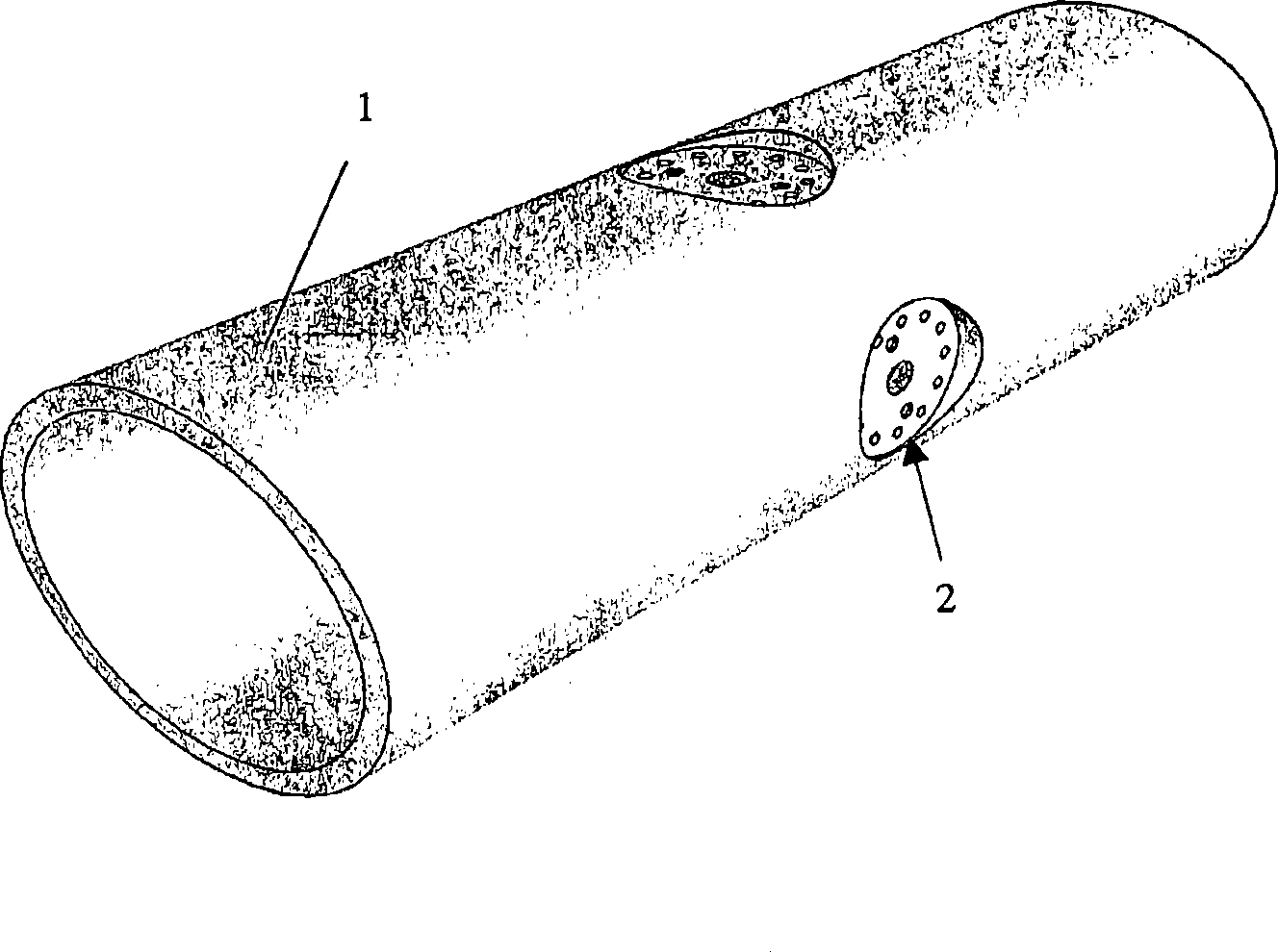
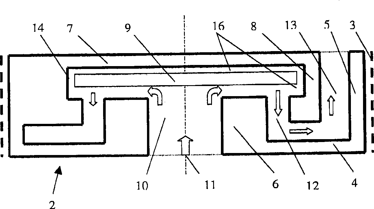
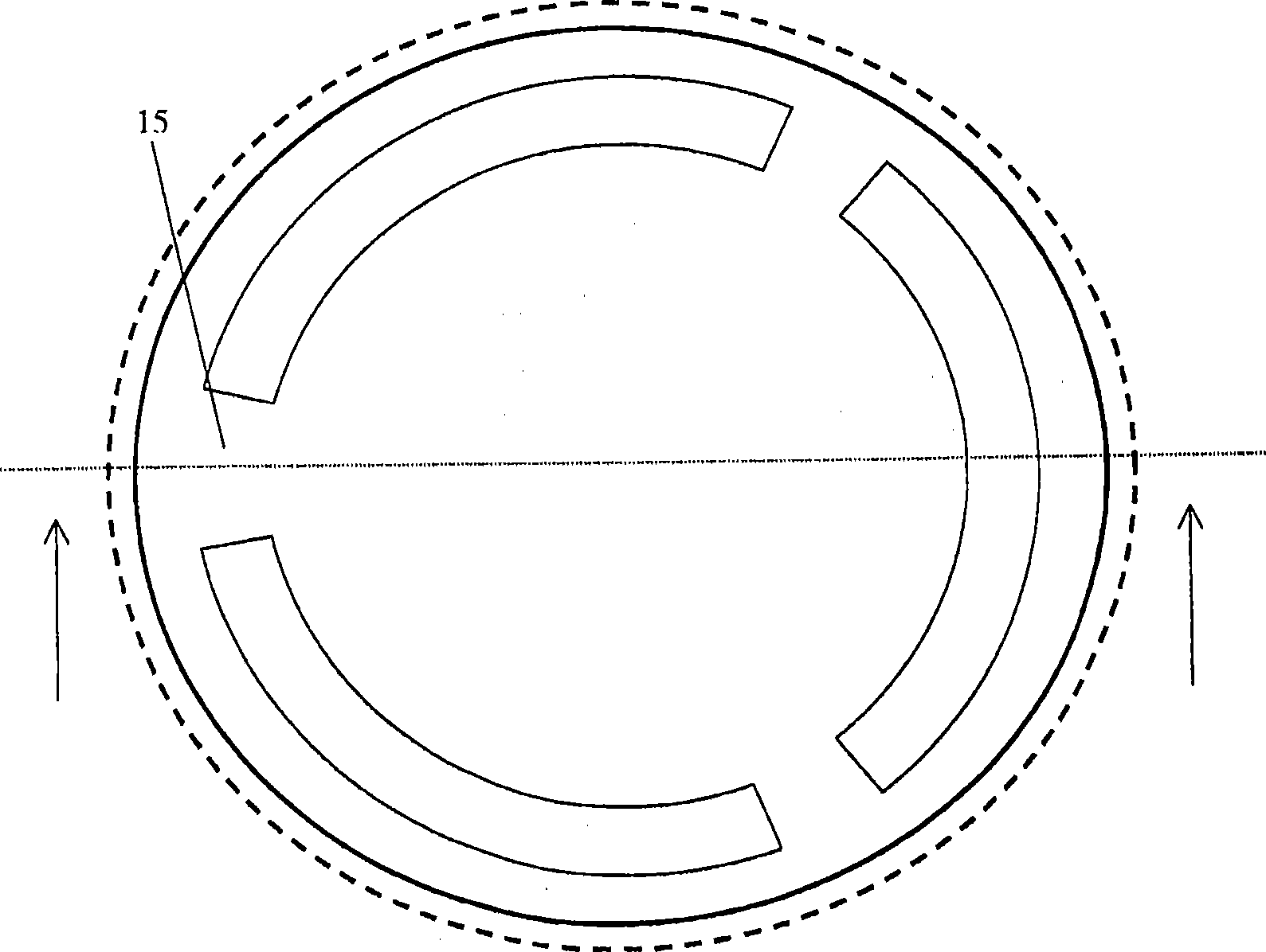
The invention relates to a method for automatically adjusting the fluid flow flowing into the production pipe for producing oil and / or gas from a well in an oil and / or gas reservoir, and a self-adjusting flow control device. The reservoir contains at least one of oil and gas. The flow control device comprises an inlet and one or more outlets. A flow path is formed between the inlet and the one or more outlets. The fluid flows through the flow path via the inlet. The fluid flows through a movable disc or a movable matrix which is designed to move relative to the inlet, thereby reducing or increasing the flow-through area of the flow control device. When the movable disc or the movable matrix is exposed to the fluid flow and some residual pressure is generated on the movable disc or the movable matrix, the movable disc or the movable matrix can move based on the Bernoulli effect. Thus, the flow control device can automatically adjust the fluid flow according to the components and the property of a fluid.
Description
technical field The present invention relates to methods for self-regulating (autonomously regulating) fluid flow through valves or flow control devices, and self-regulating valves or flow control devices for producing oil and / or gas in wells from oil and / or gas reservoirs It is particularly useful in production lines for gas, which include a lower discharge pipe, which is preferably divided into at least two sections, each section including one or more inflow control devices, the inflow control The device communicates the geological production layer with the flow space of the discharge pipe. Background technique Apparatus for recovering oil and gas from long, horizontal and vertical wells are known from US Patent Publication Nos. 4,821,801, 4,858,691, 4,577,691 and British Patent Publication No. 2169018. These known devices consist of a perforated discharge pipe with, for example, a filter for sand control around the pipe. A significant disadvantage of known devices for ...
Claims
Login to View More Application Information
Patent Timeline
 Patent Type & AuthorityApplications(China)
IPC IPC(8): E21B34/08E21B43/12
CPCE21B43/12G05D7/0146E21B34/08E21B43/32F16K15/02E21B34/00F16K15/00F16K15/023
InventorH·奥克雷V·马蒂森
OwnerDEN NORSKE STATS OLJESELSKAP AS