Automated system for handling microfluidic devices

a microfluidic chip and automatic system technology, applied in the direction of analytical using chemical indicators, laboratory glassware, instruments, etc., can solve the problems of affecting the life span of the chip when shipped and stored, the type of shipping container is undesirable, and the interaction between the dye and the surface chemistry

Active Publication Date: 2006-07-27
CAPLIPER LIFE SCI INC
View PDF23 Cites 128 Cited by
  • Summary
  • Abstract
  • Description
  • Claims
  • Application Information

AI Technical Summary

Benefits of technology

[0011] Another aspect of the present invention includes a chip that is suitable for use in the present invention that does not utilize a mount conventionally found on microfluidic chips. Such a chip may have no mount or may use an alternative mount providing for smaller overall chip size. Yet another aspect of the present invention is a microfluidic chip with or without a mount having a pierceable film covering at least one of the reservoirs. Another aspect of present invention is a cartridge for stacking, distributing and dispensing microfluidic chips, such as for use with an apparatus of the present invention.

Problems solved by technology

For example, the polymeric material of the mount 127 may cause dye interaction and surface chemistry issues with respect to the materials applied to the reservoirs.
Further, mount 127 and the adhesive used to adhere mount 127 to the working part may affect the life span of the chip when shipped and stored.
This type of shipping container is undesirable for various reasons.
First, the end user must “fish” the chip out of the fluid in which it has been shipped.
Secondly, the submersion may weaken the adhesive bonding between the laminated substrate layers in the chip, or the bonding between the working part of the chip and a mounting fixture holding the working part of the chip.
Those types of delamination may render the chip unusable.
Finally, as the chips are capable of being reused many times, the user must replace the chips into the storage fluid between uses, which increases the risk of contaminating the chip.
Although microfluidic devices have become advanced enough that multiple analyses can be performed on a single chip using very small volumes of sample material, the preparation and handling of chips often requires a great deal of human effort and time.
The reservoirs on a chip are also vulnerable to evaporation and / or current leakage between reservoirs causing changes in concentration of sample materials or in fluid flow through the chip, which can make the chip function inaccurately.
However, the microtiter plates used in conjunction with such macro-scale devices provide limited functionality as compared with microfluidic devices, since microtiter plates do not allow for the type fluid movement that can take place within microfluidic devices.
Although the macro-scale devices designed for used with microtiter plates do have some liquid handling capability, this capability is not particularly suited for the types of operations that can be performed on microfluidic chips.
Furthermore, liquid handling devices and automatic readers are not conventionally integrated into a single machine.

Method used


Image

  • Automated system for handling microfluidic devices
  • Automated system for handling microfluidic devices
  • Automated system for handling microfluidic devices

Examples


Embodiment Construction

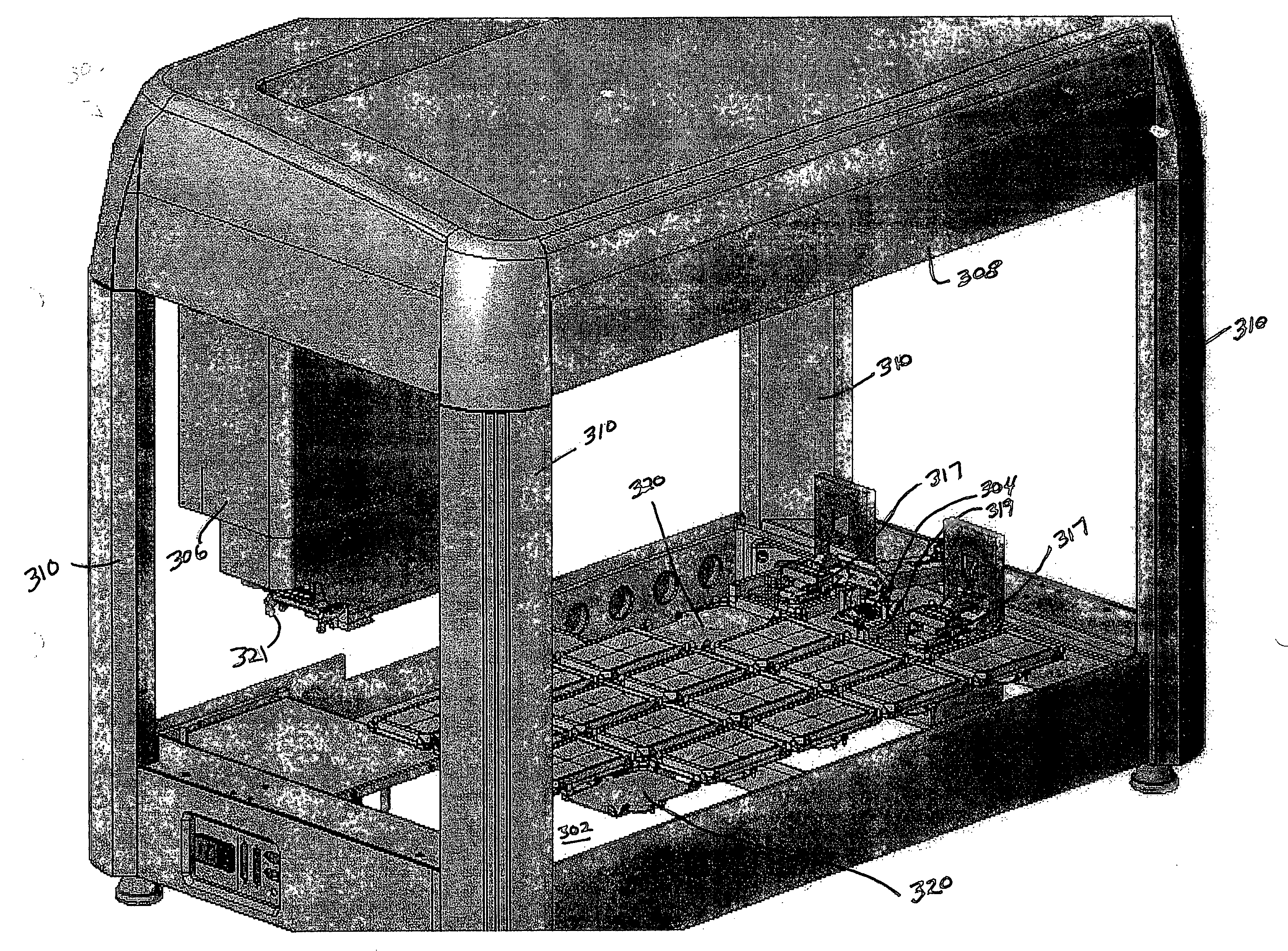
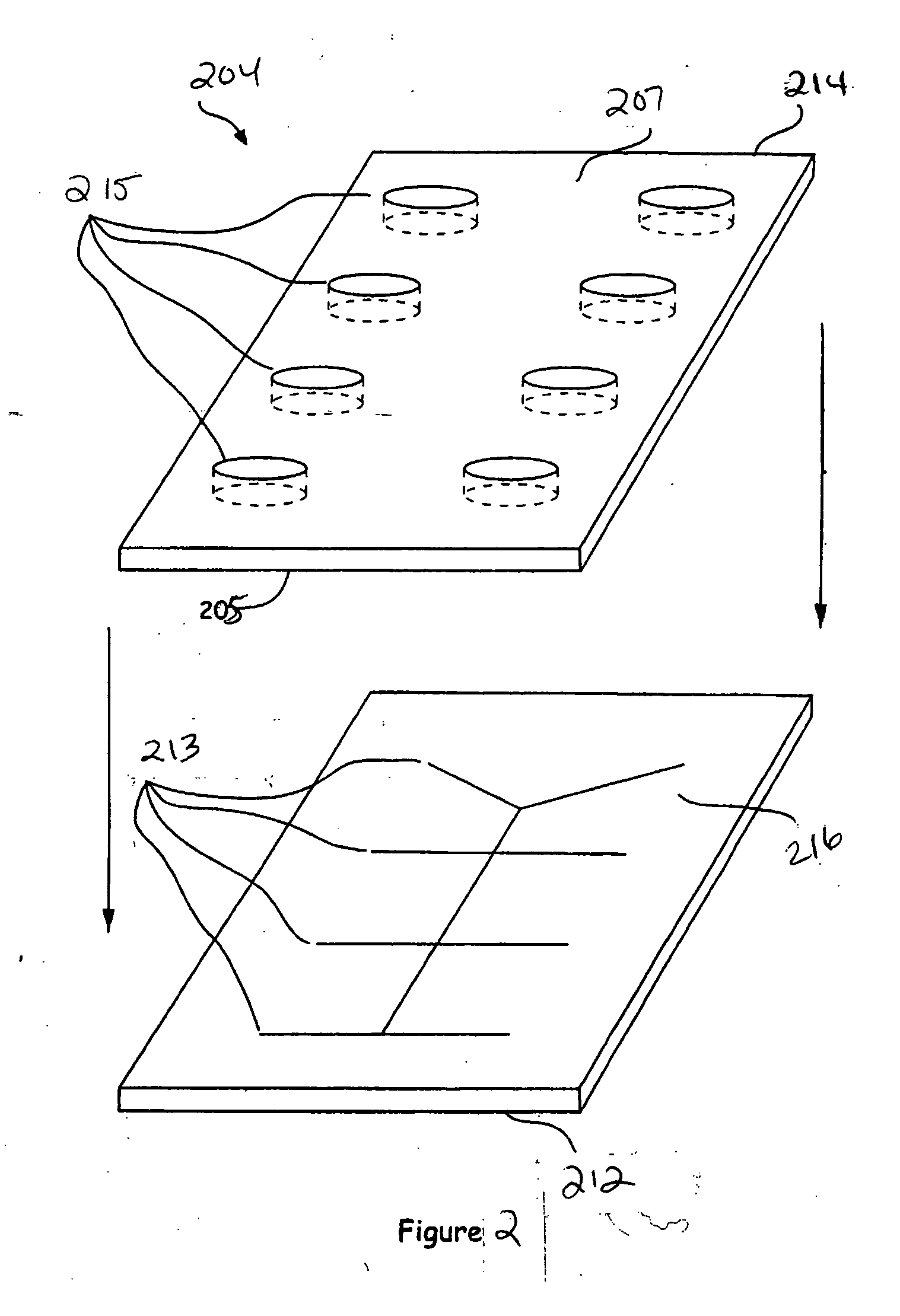
[0035] The present invention is directed towards an automated apparatus for processing a microfluidic chip. An example of a microfluidic chip 204 is illustrated in FIG. 2. The chip 204 shown is the working part of the chip without a mount. In the embodiment shown in FIG. 2, the chip 204 includes a bottom plate 212 formed from a solid substrate that is substantially planar in structure, and which has at least one substantially flat upper surface 216. The substrate could be fabricated from a variety of materials such as fused silica, glass, or plastic. In this embodiment, the channels and / or chambers of the microfluidic chip 204 are formed when grooves 213 in the upper surface 216 of the bottom plate 212, are enclosed when the bottom plate 212 is bonded to a top plate 214. The grooves can be formed in the upper surface 216 of the bottom plate by any fabrication method capable of producing microscale features in the material forming the bottom plate. For example, if the bottom plate 21...


PUM

PropertyMeasurementUnit
diametersaaaaaaaaaa
volumesaaaaaaaaaa
liquidaaaaaaaaaa

Abstract

The present invention is an automated microfluidic chip processing apparatus that includes a deck for holding at least one microfluidic chip and capable of being accessed by a liquid handling system, a fluid control system, and a detection system, wherein a chip handling device transports the chip from the deck to the fluid control system and the detection system. The present invention also includes a chip for use with an automated microfluidic chip processing apparatus, and a method for processing a microfluidic chip using such an apparatus.

Description

FIELD OF THE INVENTION [0001] This invention is generally directed to microfluidic chip devices and an automated apparatus for providing small volume, multifunction lab procedures on microfluidic chips. BACKGROUND OF THE INVENTION [0002] The use of microfluidic technology has been proposed for a number of analytical chemical and biochemical operations. This technology allows one to perform chemical and biochemical reactions, macromolecular separations, and the like, that range from the simple to the relatively complex, in easily automated, high-throughput, low-volume systems. The term “microfluidic” refers to a system or device having micron or submicron scale channels and chambers. In general, microfluidic systems include a microfluidic device, or chip, that has networks of integrated submicron channels in which materials are transported, mixed, separated and detected. Microfluidic systems typically also contain components that provide fluid driving forces to the chip and that dete...

Claims


Application Information

Patent Timeline
Patent Type & Authority Applications(United States)
IPC IPC(8): G01N35/00B01L3/00G01N21/05G01N21/11G01N21/13G01N35/02G01N35/04
CPCB01L3/5027B01L3/502715B01L9/527B01L2300/0819G01N21/05G01N21/11G01N21/13G01N35/04G01N35/1095G01N2021/058G01N35/00584G01N2021/0346
Inventor GREENSTEIN, MICHAELKENNEDY, COLIN B.MIKKELSEN, JAMES C. JR.
Owner CAPLIPER LIFE SCI INC
Why Eureka
Try Eureka