
Methods and apparatus for controlling electrolyte flow for uniform plating

a technology of uniform plating and electrolyte flow, which is applied in the direction of coatings, electrolysis components, electrolysis processes, etc., can solve the problems of uneven plating thickness and/or quality, and the quality of deposited metal films

Inactive Publication Date: 2005-11-15
NOVELLUS SYSTEMS
View PDF23 Cites 121 Cited by
  • Summary
  • Abstract
  • Description
  • Claims
  • Application Information

AI Technical Summary

Benefits of technology

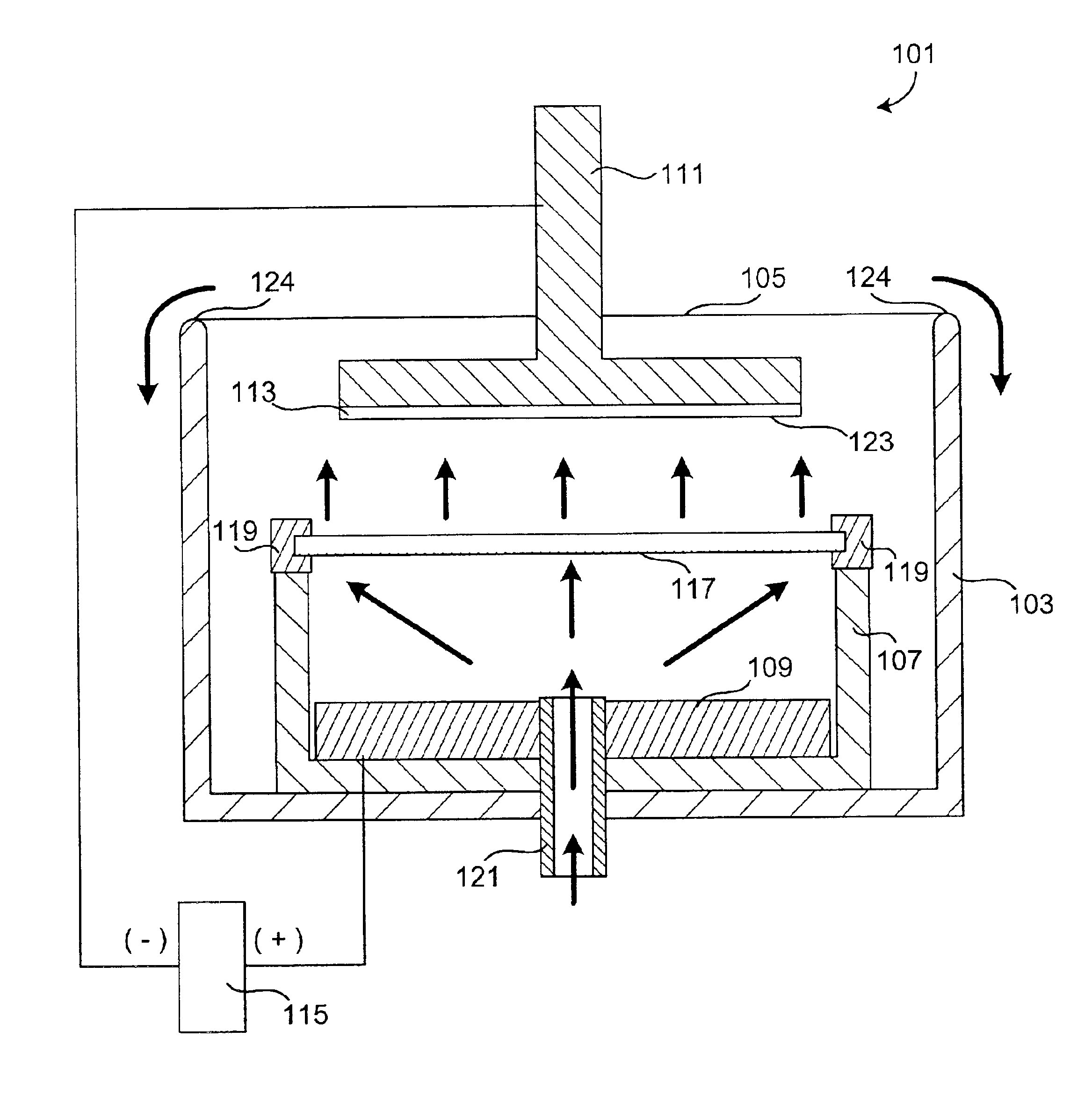
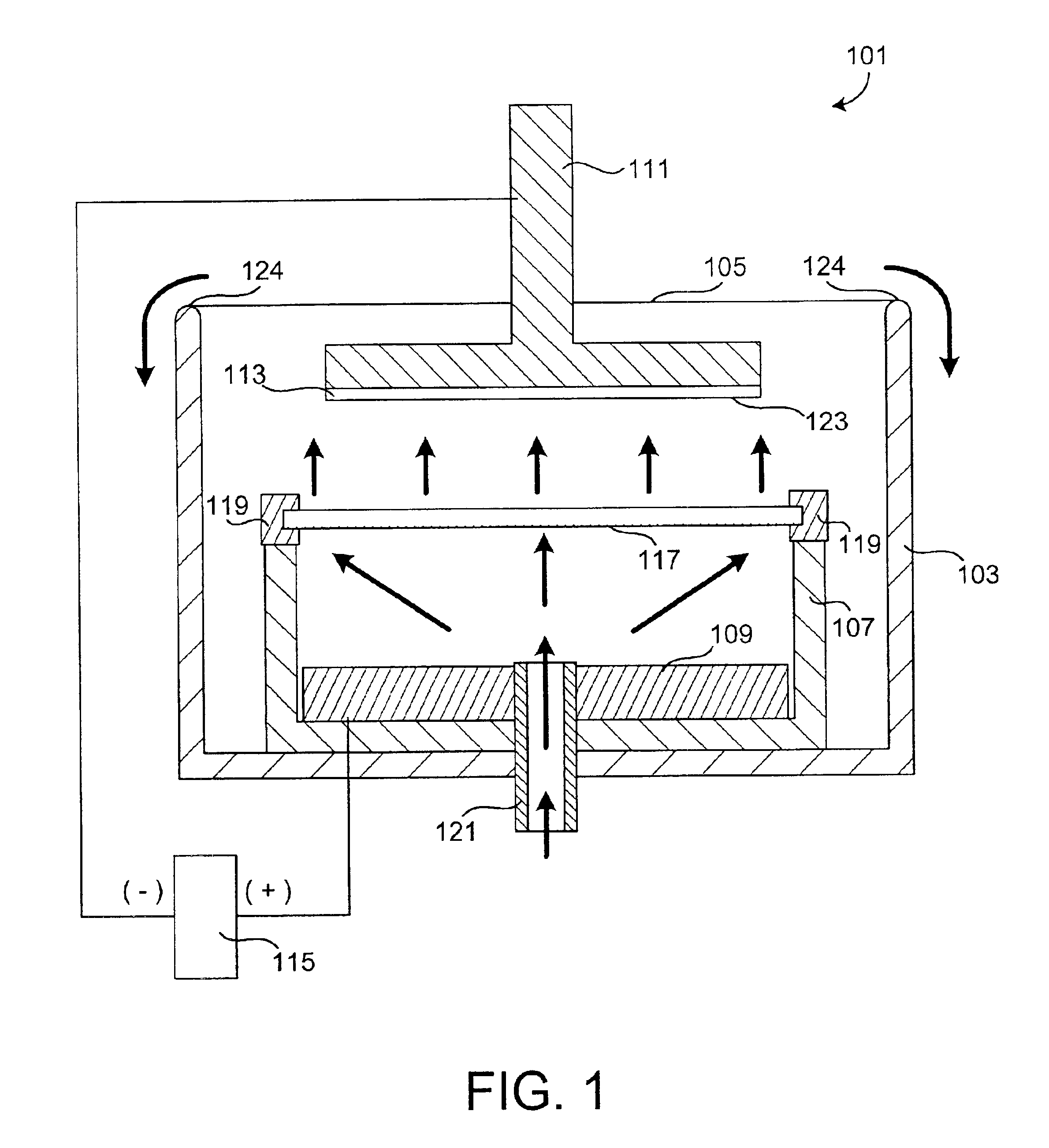
[0011]The distribution of the axial component of fluid velocity on the plating surface of a wafer is primarily important to plating uniformity. This invention controls fluid dynamics to improve film uniformity and quality. Thus, the invention provides a uniform flow of plating fluid to the plating surface of a wafer. A uniform flow in this context means a substantially uniform velocity profile across the surface of a diffuser membrane. Thus in one embodiment, a uniform flow is directed at a wafer surface along an orthogonal trajectory. Such flow patterns have been found to improve plated film quality. Particular embodiments of the invention also provide adventitious removal of bubbles and filtration of particulates, also giving improved film uniformity and quality.
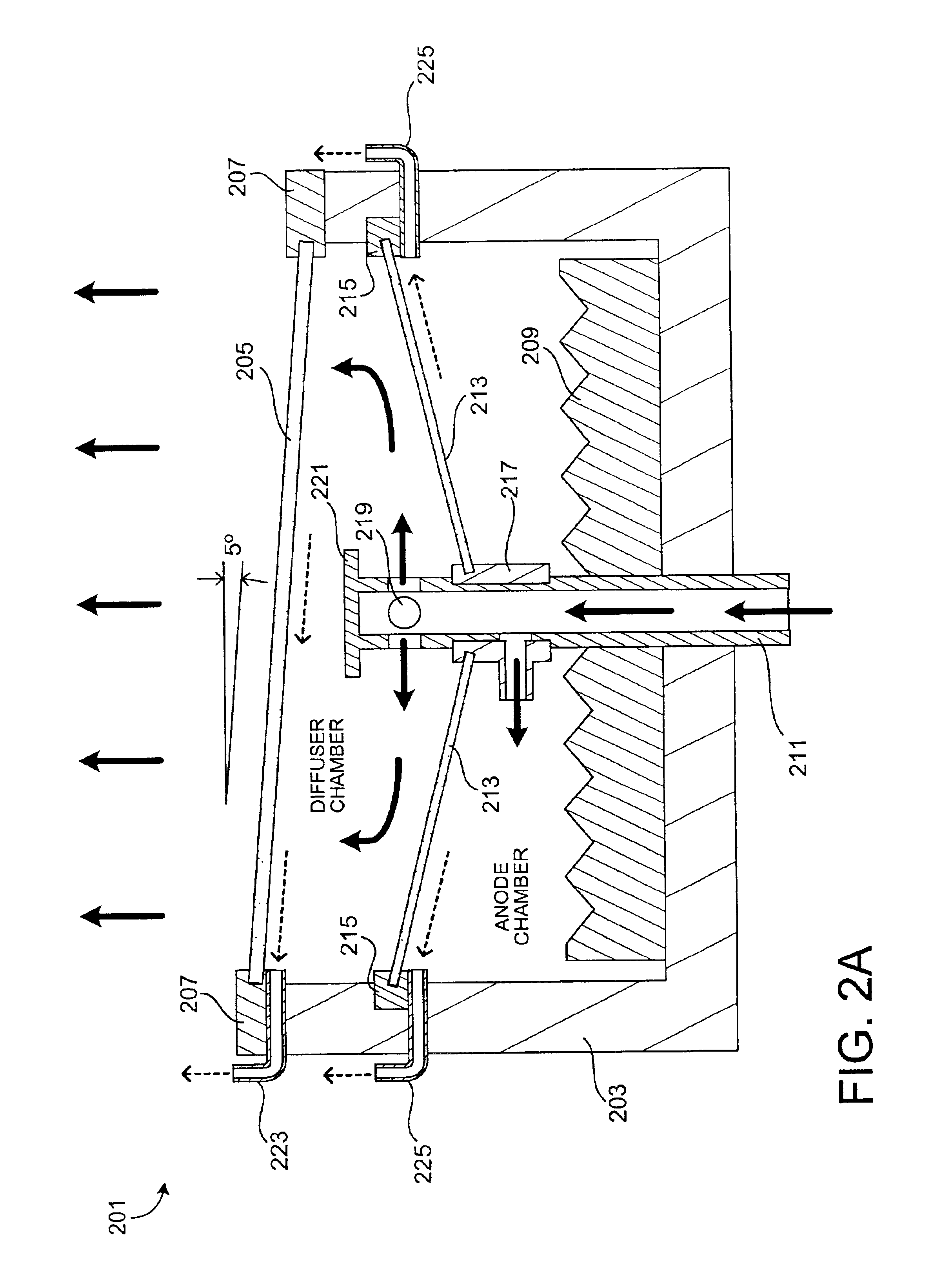
[0014]Generally, such an electroplating apparatus further comprises a mechanism for holding a planar plating surface of the substrate parallel to the diffuser membrane during plating, and optionally rotating the substrate along an axis normal to the plating surface. More particularly, a wafer can be held parallel to the diffuser membrane during plating or not, depending on the embodiment. In one embodiment, the diffuser membrane is in a tilted orientation with respect to a plane defining the surface of plating fluid in a bath that contains the anode compartment. Thus, the mechanism for holding a wafer parallel to the diffuser membrane during plating can tilt the wafer appropriately. The tilting mechanism can tilt the wafer at any time while it is in the wafer holder; that is, prior to immersion, during immersion, during plating, during extraction, or after extraction from the plating solution.

Problems solved by technology

A continuing issue in modern VLSI wafer electroplate processing is quality of the deposited metal film.
Because the plating rate and quality is a function of local velocity, this condition causes uneven plating thickness and / or quality.

Method used


Image

  • Methods and apparatus for controlling electrolyte flow for uniform plating
  • Methods and apparatus for controlling electrolyte flow for uniform plating
  • Methods and apparatus for controlling electrolyte flow for uniform plating

Examples


example 1

[0055]Modeling studies have shown that the flow from the top hole of an anode chamber flow nozzle impinges on the wafer in a jet-like fashion. This correlates with experimental data in which deposited films are thicker in the wafer center. Accordingly, the geometry of the top hole in such impinging nozzles was modified in several ways to see how such modifications effect the jet width and intensity at the wafer surface.

[0056]The five hole geometries modeled are shown in FIG. 3. FIG. 3 illustrates cross-sectional views of the following nozzle top hole geometries: 301, standard hole; 302, wide hole; 303, sloped hole; 304, flared hole; and 305, high aspect ratio hole. The dotted arrows indicated the direction of flow. To simplify analysis, side holes were closed in these models and the flow through the top was fixed at 8% of 6 liters / min. In this way the flow through each top hole would be the same as for a standard nozzle.

[0057]The realizable k-ε turbulence model was used in all cases...

example 2

[0061]FIG. 6 shows the highly uniform flow (model) achieved 1 mm from wafer surface when a diverting type nozzle, a diffuser membrane, and a slotted design clamshell with a flow path as described in FIG. 2B are used in combination. In this case, the wafer “sees” a highly uniform flow velocity across the wafer surface, with only a minimal change near the radius limit.

example 3

[0062]FIG. 7 shows a graph of pressure vs. flow rate in the anode chamber and the diffuser chamber. The graph shows actual data recorded using an anode compartment as described in FIG. 2B. The diffuser membrane was made of a sintered polyethylene produced by Portex Corporation of Fairburn, Ga. (extra fine to course grade materials). The diffuser membrane used was approximately ⅛ inch thick. The data shows that there is a measurable pressure differential between the anode chamber and the diffuser chamber.


PUM

PropertyMeasurementUnit
Fractionaaaaaaaaaa
Fractionaaaaaaaaaa
Fractionaaaaaaaaaa

Abstract

The present invention provides apparatus and methods for controlling flow dynamics of a plating fluid during a plating process. The invention achieves this fluid control through use of a diffuser membrane. Plating fluid is pumped through the membrane; the design and characteristics of the membrane provide a uniform flow pattern to the plating fluid exiting the membrane. Thus a work piece, upon which a metal or other conductive material is to be deposited, is exposed to a uniform flow of plating fluid.

Description

CROSS-REFERENCE TO RELATED APPLICATIONS[0001]This application claims priority under 35 USC 119(e) from U.S. Provisional Patent Application No. 60 / 295,116 naming Mayer et al. as inventors, titled “Methods and Apparatus for Controlling Electrolyte Flow for Uniform Plating,” filed May 31, 2001; this application is a continuation-in-part claiming priority under 35 USC 120 from U.S. patent application No. 09 / 706,272 filed Nov. 3, 2000 now U.S. Pat. No. 6,527,920, naming Mayer et al. as inventors, and titled “Copper Electroplating Method an Apparatus,” both of which are incorporated herein by reference in their entirety for all purposes. This application is also related to the following U.S. Patent Applications: U.S. Provisional Patent Application No. 60 / 295,245 naming Jonathan Reid, Steven Mayer, Marshall Stowell, Evan Patton, and Jeff Hawkins as inventors, titled “Improved Clamshell Apparatus for Electrochemically Treating Wafers,” and filed May 31, 2001; U.S. patent application No. 09 / ...

Claims


Application Information

Patent Timeline
IPC IPC(8): B05C3/00B05D1/18C25D17/00C25D5/00C25D5/08C25D7/12
CPCC25D5/08C25D7/12C25D17/00C25D7/123C25D17/001C25D17/008
Inventor MAYER, STEVEN T.STOWELL, R. MARSHALLPATTON, EVAN E.VARADARAJAN, SESHASAYEE
Owner NOVELLUS SYSTEMS
Learn More