Fluid control device

Inactive Publication Date: 2002-07-04
MEDIMOP MEDICAL PROJECTS
View PDF56 Cites 121 Cited by
  • Summary
  • Abstract
  • Description
  • Claims
  • Application Information

AI Technical Summary

Problems solved by technology

The problem of ensuring proper fluid transfer under aseptic conditions is especia

Method used


Image

  • Fluid control device
  • Fluid control device
  • Fluid control device

Examples


first embodiment

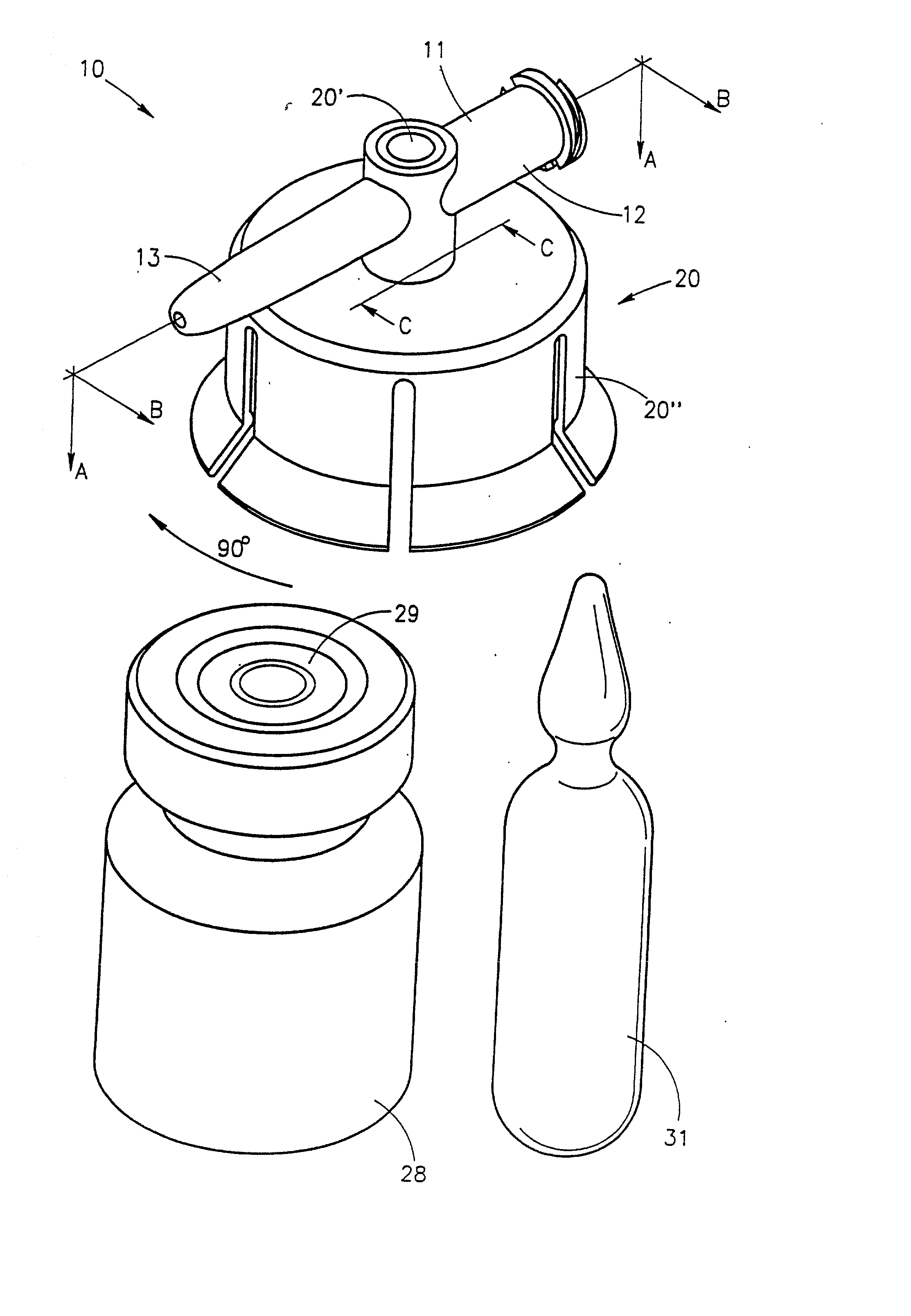
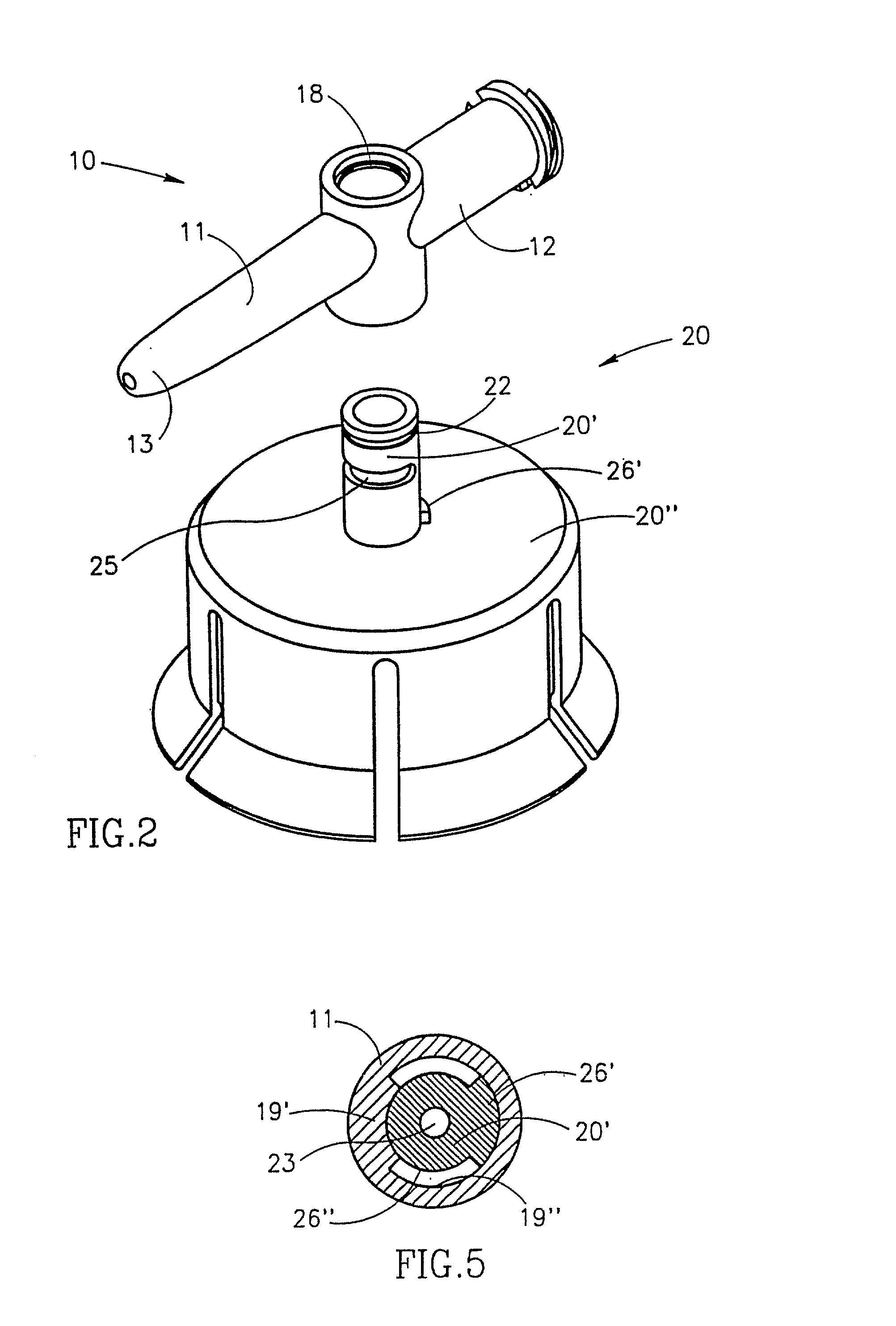
[0062] FIGS. 1-8 depict a fluid control device, generally designated 10, constructed and operative in accordance with the teachings of the present invention for enabling fluid flow control between a syringe, a medicinal vessel and a dispensing port. The fluid control device 10 includes an elongated base member 11 having a port 12 adapted for receiving a syringe and a dispensing port 13 fashioned as a plastic cannula for insertion into a pre-slit septum assembly known in the art per se. The port 12 is typically fashioned as a female luer connector.

[0063] As shown in FIG. 3, the port 12 includes a lumen 14 having an interior opening 14' and the dispensing port 13 includes a lumen 16 having an interior opening 16'. The lumens 14 and 16 are co-axial and in flow communication via a bore 17 transversely disposed relative to the elongated base member 11. The bore 17 includes an upper peripheral flange 18 and a lower minor peripheral abutment wall portion 19 protruding radially inward relat...

fourth embodiment

[0073] FIGS. 16A and 16B depict a fluid control device, generally designated 48, constructed and operative in accordance with the teachings of the present invention for enabling fluid flow control between a syringe, a medicinal vessel and a dispensing port. The fluid control device 48 is similar in construction and operation to the fluid control device 41 and therefore the same reference numerals are used where appropriate.

[0074] The main difference between the two fluid control devices 48 and 41 resides in the fact that the former includes a flow control member 49 which is required to be rotated through a 180.degree. turn between its first flow control position (see FIG. 16A) and its second flow control position (see FIG. 16B). In particular, the flow control member 49 includes an inclined channel 50 having a radial aperture 50' for registration with the interior opening 14' and an axial aperture 50" for registration with the fluid conduit member 24 so as to enable the flow path be...


PUM


Abstract

A fluid ducting assembly for enabling flow communication between a syringe and either one of a vessel and a dispenser for dispensing a fluid contained, a priori in the syringe or in the vessel. The fluid ducting assembly includes a base having a first member, a second member, and a third member for connection to and providing flow communication with the syringe, the vessel and the dispenser, respectively. The fluid ducting assembly further includes a flow controller within the base enabling any one of a flow path between the first member and the second member and a flow path between the first member and the third member. The flow controller has either a first operative position in which the flow path between the first member and the second member is enabled or a second operative position in which the flow path between the first member and the third member is enabled. The flow controller being readily switchable from its first operative position to its second operative position but not readily switchable from its second operative position to its first operative position.

Description

[0001] This is a Continuation-In-Part Application of co-pending U.S. Ser. No. 09 / 633,056 filed Aug. 8, 2000 which is a Divisional Application of U.S. Ser. No. 08 / 913,342 now U.S. Pat. No. 6,238,372B1.[0002] 1. Field of the Invention[0003] 2. Discussion of the Prior Art[0004] Drugs intended for parenteral administration are typically stored in a medicinal vessel either as a dry powder or as a solution. The solution can be ready for immediate use or in the form of a liquid concentrate which requires reconstitution with a physiological solution prior to administration in a similar manner to a dry powder drug. The physiological solution can be provided in a pre-filled syringe or a medicinal vessel.[0005] Medicinal vessels typically fall into one of three categories. The first type is a vial or a glass bottle closed by a rubber stopper which can be penetrated by a puncturing tool, for example, a needle, and which is self-closing upon withdrawal of the puncturing tool. Such a vial or glas...

Claims


Application Information

Patent Timeline
IPC IPC(8): A61J1/00A61J3/00A61J1/20A61M39/00A61M39/22
CPCA61J1/2089A61J1/2096A61J2001/201A61J2001/2013A61J2001/2058A61J2001/2062A61J2001/2075A61J2001/2082A61M5/162A61M39/18A61M39/223A61M2039/1077A61J1/201A61J1/2075A61J1/2062A61J1/2082A61J1/2013A61J1/2058
Inventor ZINGER, FREDDYDENENBURG, IGOR
Owner MEDIMOP MEDICAL PROJECTS
Why Eureka
Try Eureka