Spiral flat-tube heat exchanger

A technology of flat tubes and heat exchangers, applied in the field of counterflow heat exchangers, can solve the problems of limited performance, large ratio of height to base, high thermal resistance, etc., and achieve the effect of great flexibility

Inactive Publication Date: 2009-07-22
CARRIER CORP
View PDF0 Cites 17 Cited by
  • Summary
  • Abstract
  • Description
  • Claims
  • Application Information

AI Technical Summary

Problems solved by technology

This structure results in a relatively large height-to-base ratio
Such a height-to-base ratio limits the application of flat-plate heat exchangers
Stainless steel, commonly used in plate heat exchangers, is also relatively heavy and has a relatively high thermal resistance and low heat transfer coefficient, which also limit its performance

Method used


Image

  • Spiral flat-tube heat exchanger
  • Spiral flat-tube heat exchanger
  • Spiral flat-tube heat exchanger

Examples


Embodiment Construction

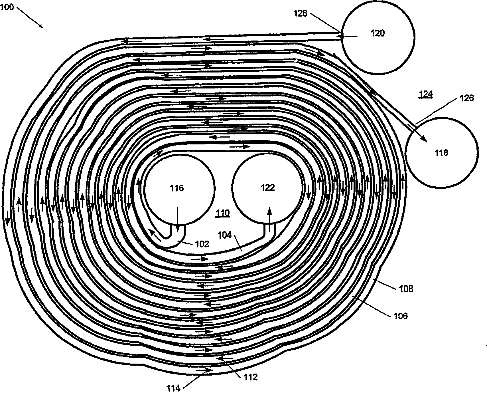
[0017] Please refer to the diagram, especially figure 1 , the embodiment of the spiral flat tube heat exchanger will be described below.

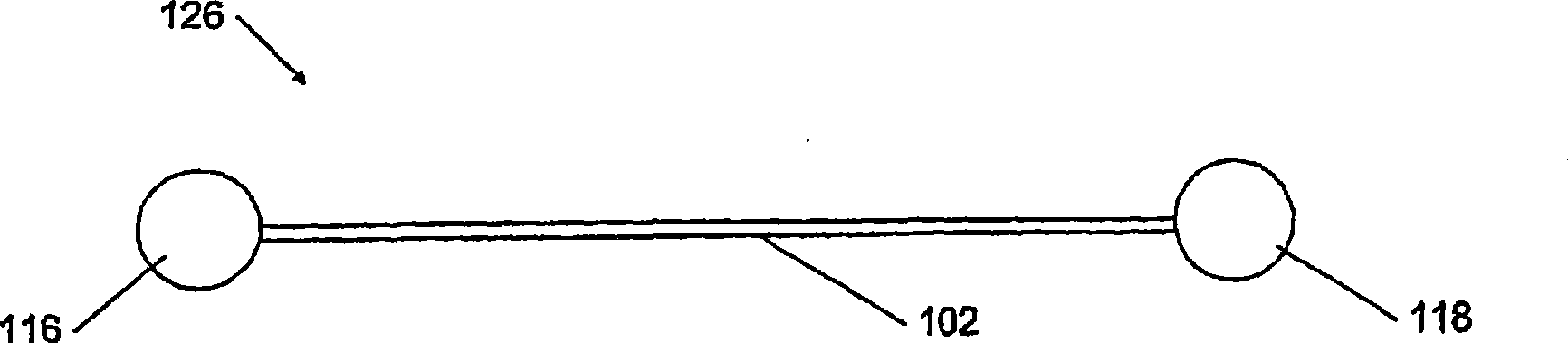
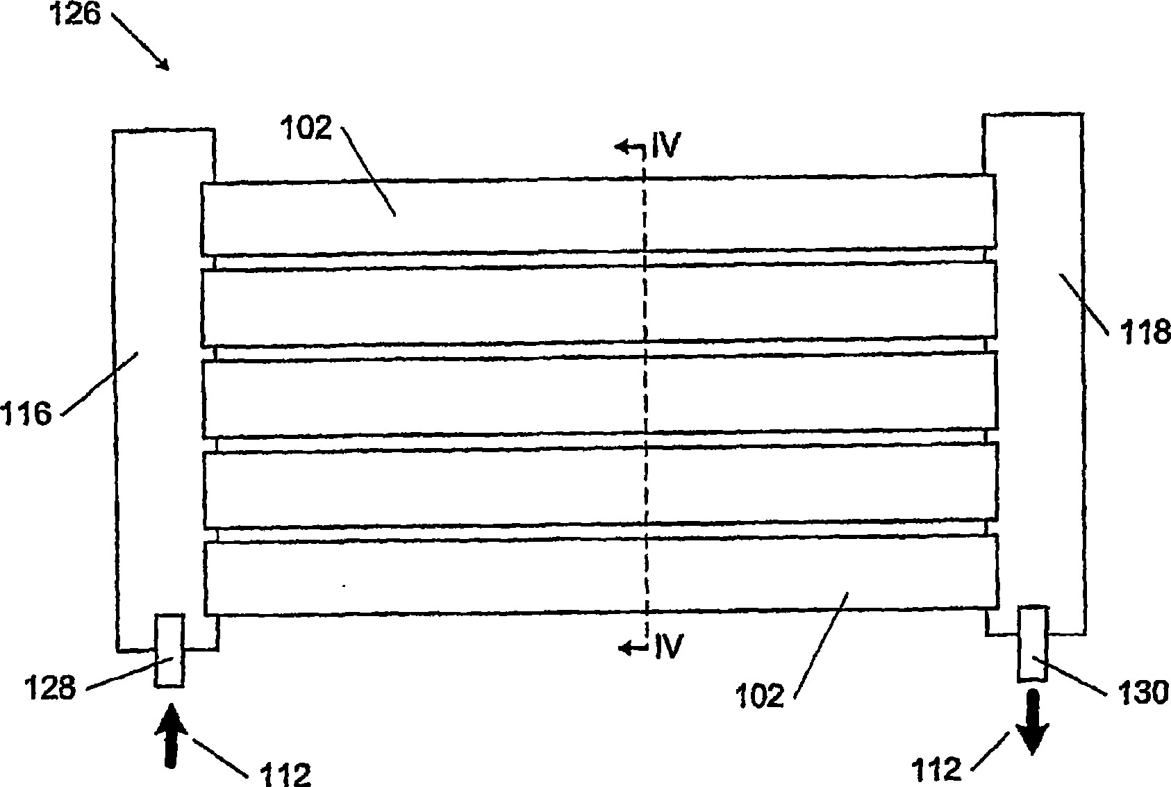
[0018] The heat exchanger 100 includes a first tube 102 and a second tube 104 . The first tube 102 is thermally coupled to the second tube 102, and the tube configuration forms an alternating helix, the helix preferably being approximately concentric. Substantially concentric means that the first helix 106 formed by the first tube 102 and the second helix 108 formed by the second tube 104 share a common central area 110 . For the purposes of this disclosure, the term helix refers to an object that surrounds a fixed central region with increasing distance from the region. A first working fluid 112 flows through the first tube 102 and a second working fluid 114 flows through the second tube 104 .

[0019] The first tube 102 and the second tube 104 are in thermal contact such that heat can be transferred between the first working fluid 112 ...


PUM


Abstract

A spiral flat tube heat exchanger comprises a first flat tube and a second flat tube thermally coupled to the first flat tube, the first flat tube and the second flat tube forming substantially concentric spirals. A first fluid flows through the first flat tube in a first flow direction, and second fluid flows through the second flat tube in a second flow direction. The flat tubes preferably contain microchannels to increase heat transfer efficiency.

Description

【Technical field】 [0001] The present invention generally relates to heat exchangers. In particular, the invention relates to counterflow heat exchangers having flat tubes arranged in concentric helices. The flattened tube may contain internal microchannels. 【Background technique】 [0002] Counterflow heat exchangers, suitable for both gases and liquids, are well known and typically include inlets and outlets for the passage of two or more fluids each. Within a heat exchanger, fluids generally do not mix and follow different flow paths. The most common types of counterflow heat exchangers include plate, tube-in-tube, and shell-and-tube heat exchangers. Shell and tube heat exchangers typically have a set of small tubes within a larger pressure vessel or shell. Heat is transferred between a fluid flowing in the small tube and another fluid flowing in the housing. [0003] In a plate heat exchanger, heat is transferred between two fluids flowing in opposite directions along...

Claims


Application Information

Patent Timeline
Patent Type & Authority Applications(China)
IPC IPC(8): F28D7/14
CPCF28D2021/0071F28D7/0033F28F2013/006F28D7/04F28F2260/02F28F2275/025F28D2021/007Y10T29/4935
Inventor M·格拉邦
Owner CARRIER CORP
Why Eureka
Try Eureka