
Light source lighting circuit on stereomicroscope

A stereo microscope and microscope technology, applied in microscopes, light sources, lighting devices, etc., can solve the problems of exposed wires, inconvenient disassembly of the main body and base, and the inability of the light source to rotate freely with the main body.

Inactive Publication Date: 2009-07-29
MOTIC CHINA GRP CO LTD
View PDF0 Cites 2 Cited by
  • Summary
  • Abstract
  • Description
  • Claims
  • Application Information

AI Technical Summary

Problems solved by technology

In these situations, when using the upper light source for lighting, it needs to be directly connected to the luminous body on the main body through the wire connected to the power supply, which often causes the wire to be exposed, which makes it very inconvenient to disassemble the main body and the base.
[0004] Of course, in the lighting of the upper light source, there are also power wires connected to the light source built inside the body, and whether the power wire is inside or outside the body, since the light source and power wire belong to the traditional two-point and one-line fixed connection method, the rotation of the light source is inevitable. Limited by the wrapping of the wire connections, the light source cannot freely rotate with the subject and therefore cannot provide a clear field of view in the direction of subject rotation

Method used


Image

  • Light source lighting circuit on stereomicroscope
  • Light source lighting circuit on stereomicroscope
  • Light source lighting circuit on stereomicroscope

Examples


Embodiment Construction

[0029] The present invention will be further described below in conjunction with the accompanying drawings and specific examples.

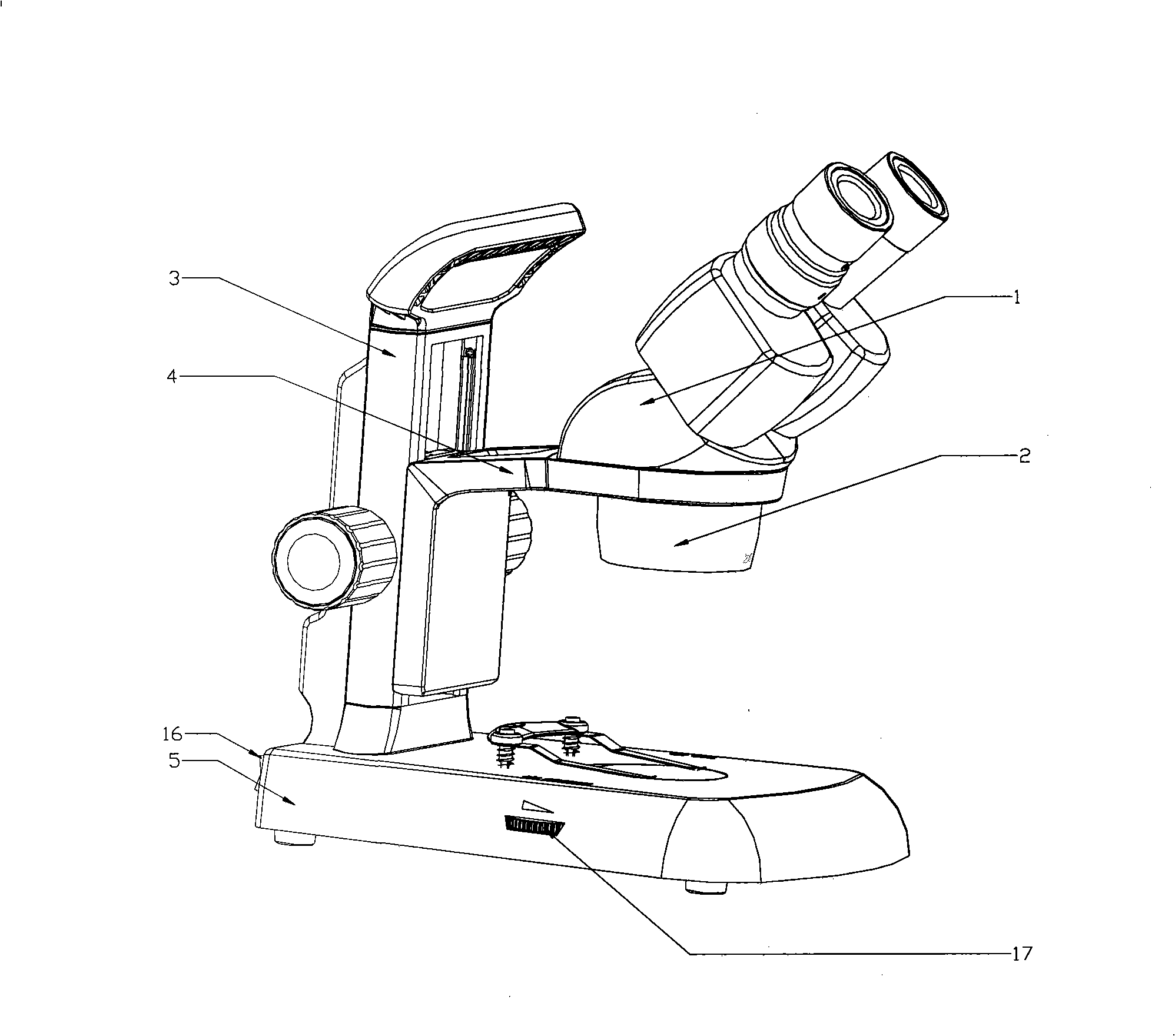
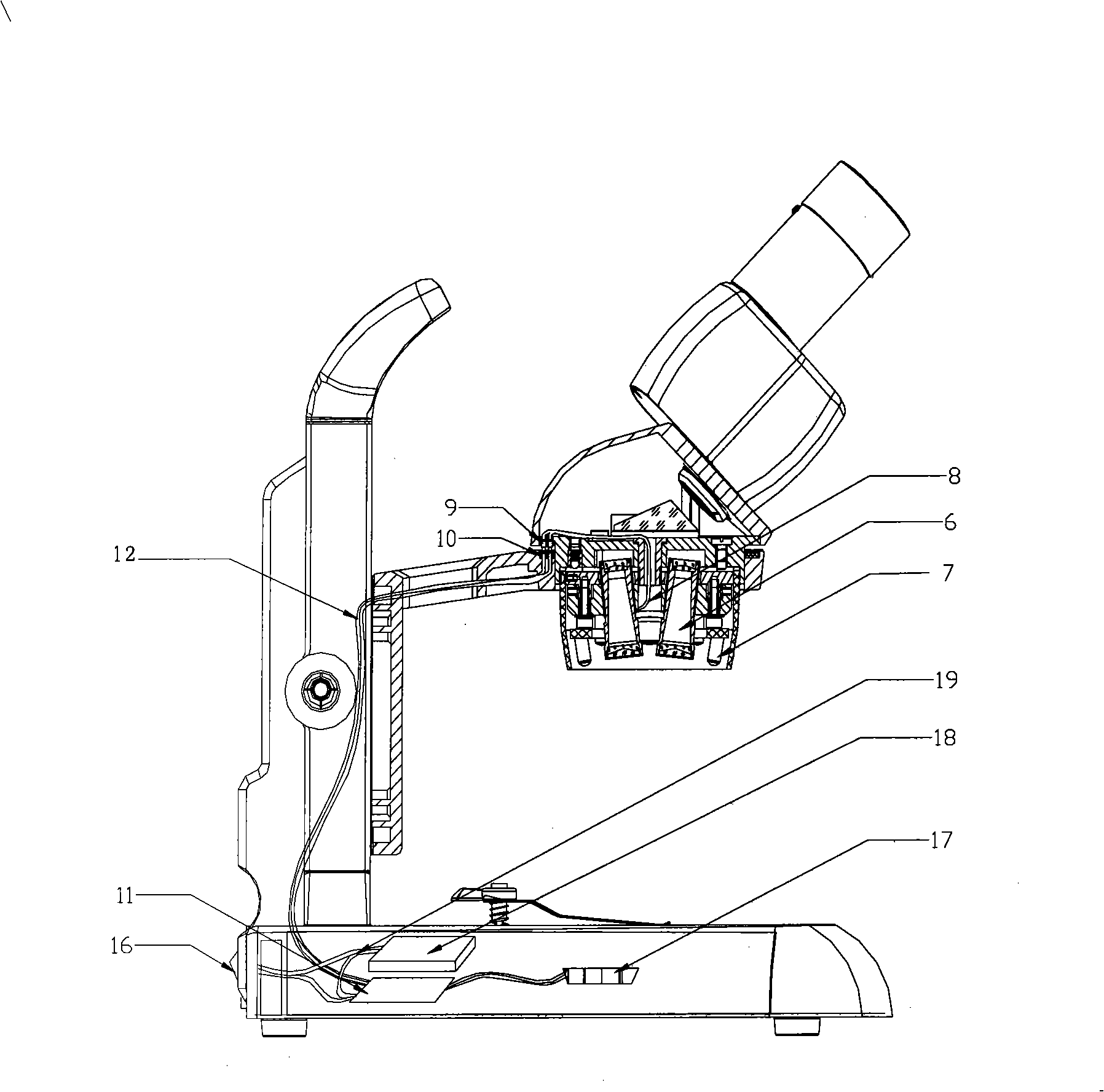
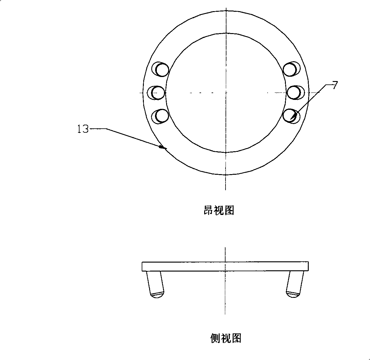
[0030] Such as figure 1 , 2 As shown, in this example, because LED has the characteristics of cold light source and good lighting effect, LED7 is selected as the light group for the above light source lighting. The present invention is made up of LED7, two pogo pins 9, two independent ring-shaped conductive rails 10 and a switch. The LED7 installed on the circuit board is installed in the objective lens cover 2 as required. The plane where it is located is parallel to the cross-section below the objective lens cover 2; the cathode and anode of the LED7 are respectively connected to two pogo pins 9, and the two circular conductive tracks 10 are respectively connected to the circuit board connected to the cathode and anode of the power supply. Each pogo pin 9 is connected with two conductive rails 10 anodes and cathodes corresponding contact conne...


PUM


Abstract

The invention provides a light source lamp circuit on a stereomicroscope, comprising a fixed component and a slide component which are opposite; wherein the slide component comprises an object lens and an observation device. The invention is characterized in that the fixed component is formed by two independent ring-shaped conducting rails, the two ring-shaped conducting rails are respectively connected with a circuit board connected with the cathode and the anode of a power source; two spring thimbles and a plurality of lamp sets are arranged in the sliding component, the two spring thimbles are respectively connected with the cathode and the anode of an LED; when the slide component is arranged in the fixed component, the two spring thimbles are respectively contacted with the conducting rails for conduction, thus being convenient for a user to use the stereomicroscope at any angle; the light source can freely rotate along with main body without being restricted by a connecting wire, thus providing the main body with clear visual field; and if the LED is used as the lamp set, illuminating effect of the lamp set is improved.

Description

technical field [0001] The invention relates to a light source lighting circuit on a stereo microscope. Background technique [0002] Illumination sources for stereo microscopes include natural light and artificial light. Natural light is not bright enough to observe the object after imaging through the microscope, which is limited in use. Therefore, microscopes generally require additional lighting. The illumination methods of stereo microscopes usually include transmitted illumination (lower light source) and reflective illumination (upper light source). The lower light source is located in the base of the microscope and is mainly used for observing slices, grid plates, resolution plates, etc. Due to the directness of the upper lighting, it not only increases the brightness but also increases the viewing angle, so the use of the upper light source lighting has a great advantage. The upper light source lighting has been widely used, but the position of the upper light so...

Claims


Application Information

Patent Timeline
IPC IPC(8): F21V33/00F21V21/35G02B21/06F21Y101/02
Inventor 陈东明陈玉嫦邓昌荣
Owner MOTIC CHINA GRP CO LTD
Learn More