Method, system and network appliance for fault recovery

A technology for fault recovery and network equipment, applied in the field of communication, can solve problems such as increasing the degree of resource conflict, reducing the network fault recovery rate, and increasing the network fault recovery time.

Active Publication Date: 2009-07-29
HUAWEI TECH CO LTD +1
View PDF0 Cites 6 Cited by
  • Summary
  • Abstract
  • Description
  • Claims
  • Application Information

AI Technical Summary

Problems solved by technology

[0005] It can be seen that when there are a large number of working connections passing through the fault point in the network, the use of the above fault r

Method used


Image

  • Method, system and network appliance for fault recovery
  • Method, system and network appliance for fault recovery
  • Method, system and network appliance for fault recovery

Examples


Embodiment Construction

[0019] Embodiments of the present invention provide a fault recovery method, a fault recovery system, and corresponding detection node network equipment and working node network equipment, which will be described in detail below.

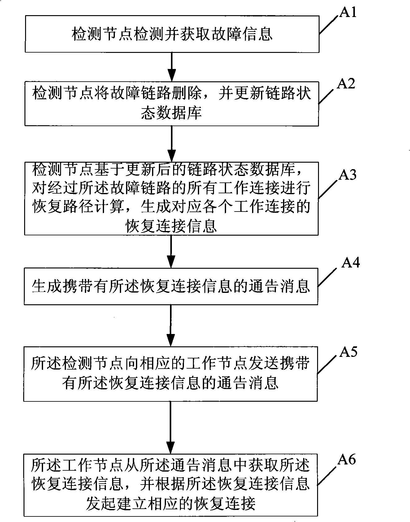
[0020] refer to figure 2 , is a schematic flowchart of a fault recovery method in an embodiment of the present invention, including steps:

[0021] A1. The detection node detects and obtains fault information.

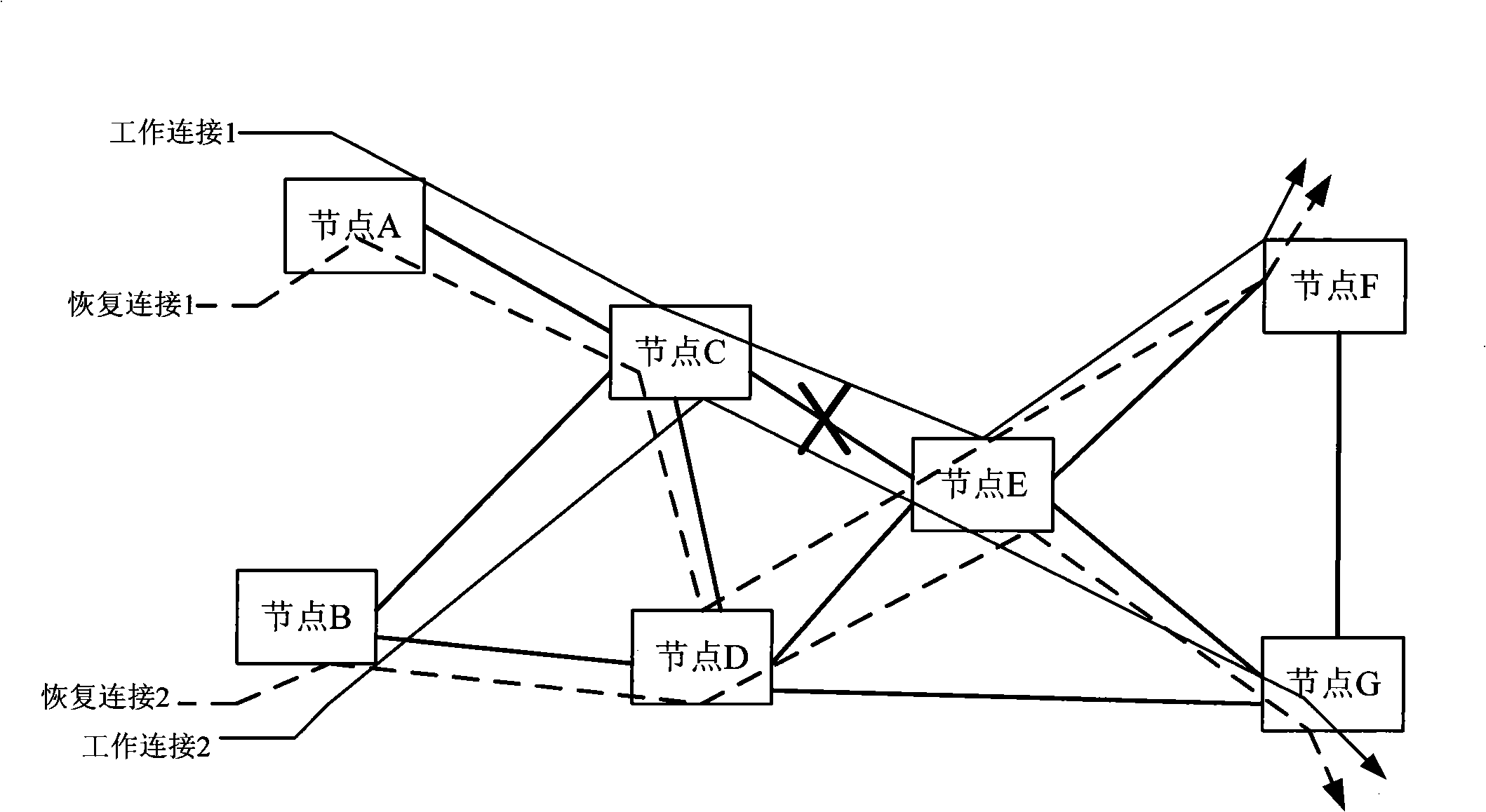
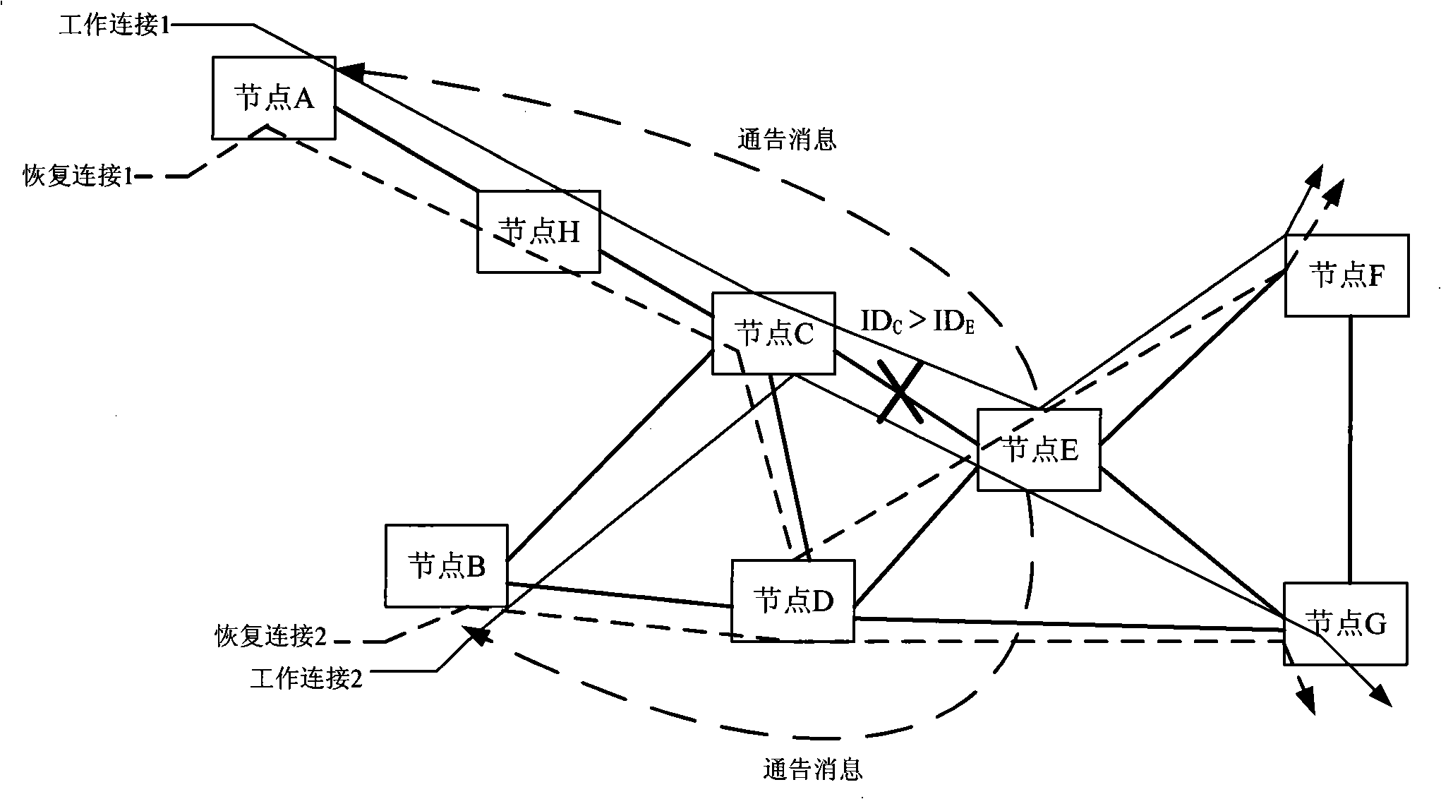
[0022] refer to image 3 , the schematic diagram of the first embodiment of the fault recovery system of the present invention, when image 3 When the link shown is faulty, the upstream and downstream nodes node C and node E of the faulty link can detect the link fault through the existing fault detection mechanism. The detection node described above; when a Figure 4 When the transmission plane node shown fails, the control plane node corresponding to the transmission plane node will detect the corresponding failure. At this time, the ...


PUM


Abstract

The invention provides a failure recovery method, which comprises: when a failure occurs, a detection node determines the recovery connection of the work connection influenced by the failure; the detection node sends the recovery connection information to the work node corresponding to the work connection influenced by the failure; the work node acquires the recovery connection information and establishes corresponding recovery connection according to the recovery connection information. The invention further provides corresponding failure recovery system, detection node network equipment andwork node network equipment. By the calculating of recovery connection and the informing are performed by the detection node network equipment in concentration, the invention effectively avoids resource conflict, reduces connection return in the network, and reduces network failure recovery time.

Description

technical field [0001] The invention relates to the communication field, in particular to a fault recovery method, a fault recovery system and network equipment. Background technique [0002] Automatic Switched Optical Network (ASON, Auto Switch Optical Network) / Generalized Multi-Protocol Label Switching Network (GMPLS, Generalized Multi-Protocol Label Switch) network introduces the control plane, which transfers some control functions originally implemented by the network management from the management plane to the On the control plane, it gradually develops from the centralized control of the network management to the distributed control of intelligent nodes. At present, the network fault recovery technology generally adopts the method of distributed source node processing. The network node that detects the fault point notifies the information of the fault point to multiple source nodes of the links affected by the fault through distributed control signaling. Compute new...

Claims


Application Information

Patent Timeline
IPC IPC(8): H04Q11/00H04B10/08
Inventor 陆月明王淼纪越峰章发太高建华
Owner HUAWEI TECH CO LTD
Why Eureka
Try Eureka