Hydraulic pressure booster for ultra-high pressure tool

A hydraulic supercharger, ultra-high pressure technology, applied in the direction of fluid pressure converter, fluid pressure actuating device, servo motor components, etc. The effect of strong pollution, long service life and extended service life

Inactive Publication Date: 2009-08-05
BEIJING UNION UNIVERSITY
View PDF0 Cites 20 Cited by
  • Summary
  • Abstract
  • Description
  • Claims
  • Application Information

AI Technical Summary

Problems solved by technology

The hydraulic booster can overcome the defects of large leakage, poor anti-pollution

Method used


Image

  • Hydraulic pressure booster for ultra-high pressure tool
  • Hydraulic pressure booster for ultra-high pressure tool
  • Hydraulic pressure booster for ultra-high pressure tool

Examples


Embodiment Construction

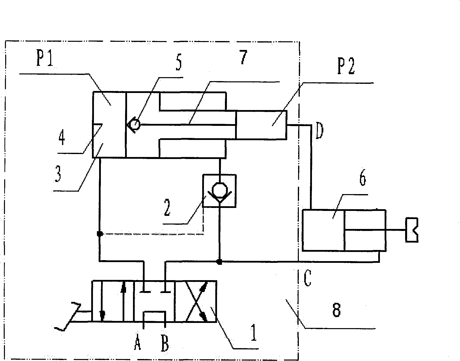
[0029] like figure 1 As shown, the booster 8 of the present invention uses a booster cylinder 3, a conventional pressure element reversing valve 1, and a hydraulic control check valve 2 to form a booster circuit. The booster cylinder 3 is provided with a booster cylinder piston, and the booster cylinder piston separates the booster cylinder into a rodless cavity, a rod cavity and a booster cavity. A push rod 4 is arranged on the end cover of the rodless chamber of the pressurized cylinder. The piston of the booster cylinder is a hollow part, and a check valve 5 and a central hole 7 are arranged in the hollow, and communicate with the pressurization chamber P2. When the piston is fully retracted, the push rod will touch the one-way valve 5 to conduct it, and the outlet end of the one-way valve 5 communicates with the pressurization chamber P2 through the central hole 7 . The pressurized cylinder 3 has a hydraulic control check valve 2 on the oil circuit of the rod cavity.

...


PUM


Abstract

The invention belongs to the field of the hydraulic device, in particular relates to a hydraulic intensifier (8) of a superhigh pressure tool. The hydraulic intensifier (8) adopts a pressure cylinder (3), a reversing valve (1) and a hydraulic control one-way valve (2) to form a pressurizing loop, a pressure cylinder piston is arranged in the pressure cylinder (3) and is used for dividing the pressure cylinder into a poleless cavity, a pole cavity and a pressurizing cavity, a top pole (4) is arranged on an end cover of the poleless cavity of the pressure cylinder, the pressure cylinder piston is a hollow part, an one-way valve (5), a center hole (7) and the pressurizing cavity are arranged in the hollow, and the inlet end of the one-way valve (5) is positioned in a position which opposites to the top pole (4). When the piston completely withdraws, the top pole can touch the one-way valve (5) to communicate the one-way valve, the outlet end of the one-way valve (5) is communicated with the pressurizing cavity by the center hole (7), and the hydraulic control one-way valve (2) is arranged on an oil circuit of the pole cavity of the pressure cylinder (3). The hydraulic intensifier has compact structure, and the pipeline connection between the valves and the pressure cylinders is saved to reduce system leakage. The invention has the advantages of convenient installation, low cost, stable operation, long service life, high work efficiency, strong temperature variation resistance, strong environmental pollution resistance, convenient maintenance, and the like and is suitable for the outdoor service on building sites for a long period.

Description

technical field [0001] The invention belongs to the field of hydraulic equipment, in particular to a hydraulic pressure booster for ultra-high pressure tools. Background technique [0002] In the hydraulic systems of ultra-high pressure tools such as steel shearing, extrusion connection and expander currently used, ultra-high pressure oil pumps are usually used as the power source of the equipment. [0003] The ultra-high pressure oil pump is a conversion device that converts the mechanical energy output by the motor (or other prime mover) into liquid ultra-high pressure pressure energy (80-100MPa). The ultra-high pressure oil pump has the advantages of small size, light weight, and large output force, and is suitable for use as a hydraulic power source for ultra-high pressure tools. However, in actual use, it is also found that there are some problems with the ultra-high pressure oil pump: [0004] 1) The flow rate of the ultra-high pressure oil pump itself is small, and ...

Claims


Application Information

Patent Timeline
IPC IPC(8): F15B3/00F15B15/14F15B13/02
Inventor 毛智勇陈瑞阳刘建
Owner BEIJING UNION UNIVERSITY
Why Eureka
Try Eureka