Eureka AIR delivers breakthrough ideas for toughest innovation challenges, trusted by R&D personnel around the world.

Electric valve

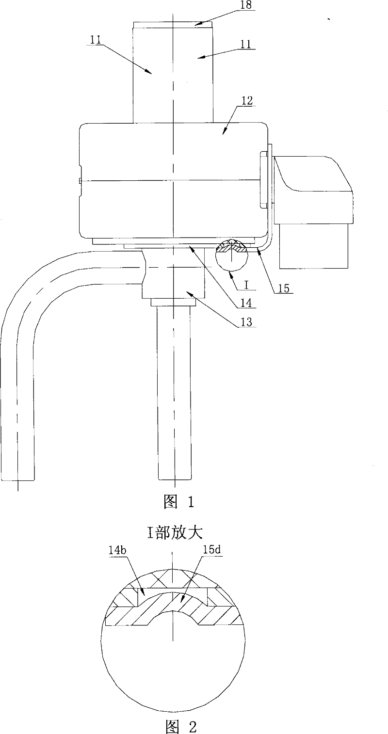
An electric valve and valve seat technology, applied in the direction of valve lift, valve details, valve device, etc., can solve the problems of poor axial positioning ability of the coil and loose coil positioning, and achieve the effect of ensuring dryness, reliable fixing relationship and ensuring elasticity.

Active Publication Date: 2012-01-11
ZHEJIANG SANHUA INTELLIGENT CONTROLS CO LTD
View PDF1 Cites 0 Cited by
  • Summary
  • Abstract
  • Description
  • Claims
  • Application Information

AI Technical Summary

Problems solved by technology

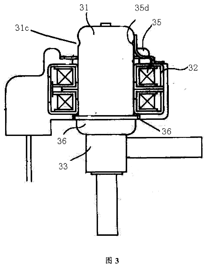
This solution improves the reliability of the product under high pressure to a certain extent, but the axial positioning ability of the coil is poor, and it is easy to cause loose coil positioning under the condition of repeated vibration of the system

Method used


Image

  • Electric valve
  • Electric valve
  • Electric valve

Examples


Embodiment Construction

[0037] The following describes the implementation in detail in conjunction with the accompanying drawings.

[0038] The electric valve of the present invention realizes the reliable positioning of the coil by improving the structure and connection relationship between the coil fixing frame and the positioning card; at the same time, the matching relationship between the welding parts is combined with the optimally designed weld position to improve the electric valve. High pressure capability.

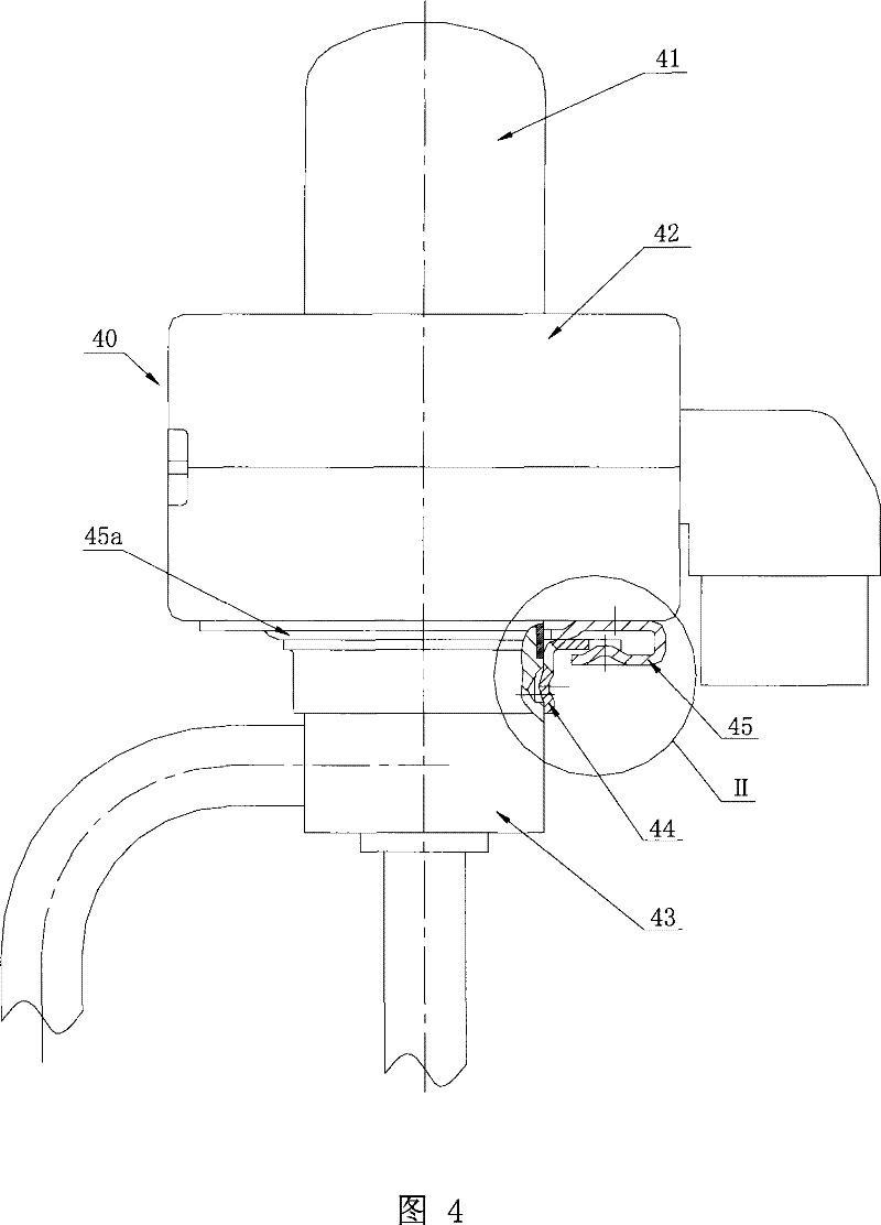
[0039] see Figure 4 , which is a schematic diagram of the overall structure of the present invention.

[0040] The main structure of the solenoid valve of the present invention is the same as that of the prior art. As shown in this figure, it includes a magnetic rotor (not shown) and a valve needle (not shown) placed in the housing 41, a stator 40, a valve seat 43, a positioning card 45 and a coil holder 44; wherein, the stator 40 is a yoke made of a coil box 42, a soft magnetic mate...


PUM


Abstract

The invention discloses an electric valve, with key designing points as follows: the structures and the connection relation of coil holders and positioning cards are improved, and the cooperation relations between welding parts are combined with optimally designed welding positions, so that the reliable positioning of the coils is achieved, and the high-pressure resistant capability of the electric valve is improved; wherein the outer edges of the positioning cards fixed on coil cases detour internally to form circuitous parts after extending downwards; the outer edges of the coil holders fixed on valve bases extend out of a limit baffle on which a spacing groove is arranged; the limit baffle is placed in containing parts of the positioning cards; and the top ends of positioning salient points on the circuitous parts of the positioning cards are blocked in the spacing groove. In addition, an annular groove is designed on the valve bases at the lower part of the welding joints to partially cut the influence of the vibration of the valve bases and coils on welding joints. The invention has the advantages of compact structure, and good assembling and operation, and is especially suitable for such electric appliances as refrigerators, air-conditioner cooler units, water heaters and dehumidifiers.

Description

technical field [0001] The invention relates to a valve, in particular to an electric valve. Background technique [0002] At present, the electric valve used in the refrigeration system is driven by a stepper motor, and the opening of the valve is adjustable to control the flow of the medium in the pipeline. [0003] The electric valve with conventional structure includes a casing, an electromagnetic coil set outside the casing, a valve seat connected to the lower part of the casing, and a magnetic rotor, valve needle and valve seat located in the casing; the casing is made of non-magnetic materials such as stainless steel It has a cylindrical structure and is welded to the valve seat; the stator is composed of a yoke iron made of soft magnetic material and a stator coil wound through a coil barrel in the yoke iron. The stator and the rotor form a stepping motor for driving the valve needle Engagement or disengagement with respect to the valve seat. When the system is wor...

Claims


Application Information

Patent Timeline
Patent Type & Authority Patents(China)
IPC IPC(8): F16K31/04F16K1/38
Inventor 袁泽詹才意蒋炜炜陈伯汀
Owner ZHEJIANG SANHUA INTELLIGENT CONTROLS CO LTD
Why Eureka
Eureka Blog
Learn More