Vacuum absorption adjusting platform for milling and grinding

A vacuum adsorption and adjustment table technology, which is applied in the direction of grinding machines, optical surface grinders, grinding/polishing equipment, etc., can solve the position change of milling and grinding vertices, reduce the milling and grinding precision, and the radial and axial non-uniform errors of the position of optical components To achieve the effect of compensating the error of uneven distribution of axial deformation, ensuring positioning accuracy and realizing flexible sealing

Active Publication Date: 2017-12-08
DALIAN INST OF CHEM PHYSICS CHINESE ACAD OF SCI
View PDF10 Cites 0 Cited by
  • Summary
  • Abstract
  • Description
  • Claims
  • Application Information

AI Technical Summary

Problems solved by technology

But it is precisely because of this soft contact method that the position of the optical element will produce radial and axial non-uniform errors before and after adsorption, which makes it difficult to ensure the parallelism of the milled flat optical element, and leads to spherical and Aspheric milling vertex position changes, reducing milling precision
Moreover, since milling and grinding cannot be completed in one step, there must always be inspections interspersed in the middle, and the soft contact of vacuum adsorption will increase the uncertainty of the fixed position of the component after each milling and grinding
These are not conducive to high-precision milling of optical components

Method used


Image

  • Vacuum absorption adjusting platform for milling and grinding
  • Vacuum absorption adjusting platform for milling and grinding

Examples


Embodiment Construction

[0020] The following will take the accompanying drawings as an example to illustrate the connotation of the present invention. Any insubstantial improvements and embellishments made by those skilled in the art on the basis of the present invention fall within the scope of the present invention.

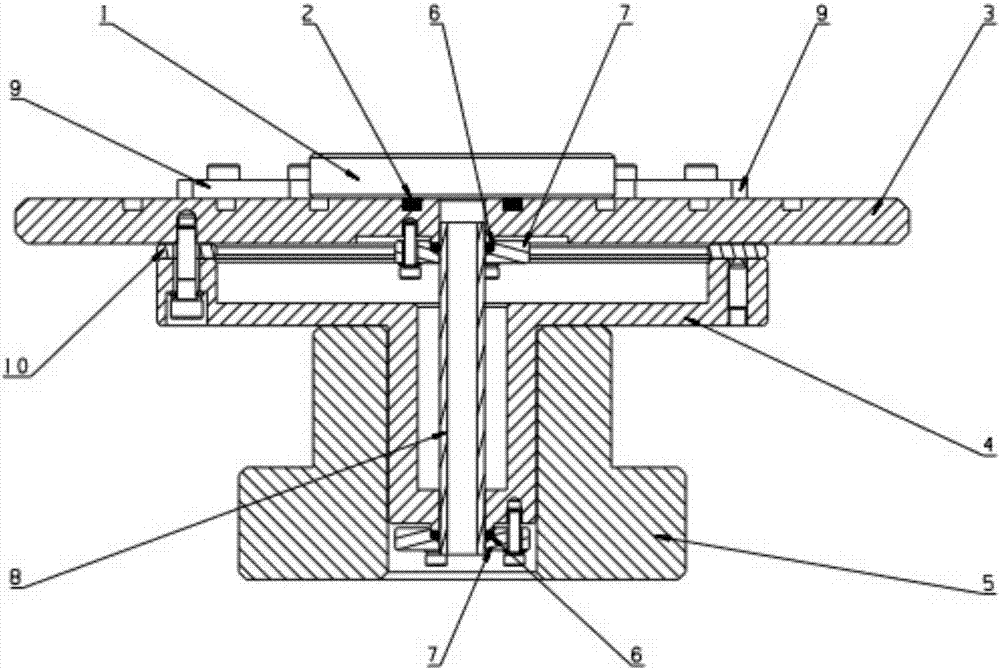
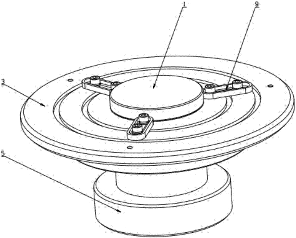
[0021] Such as figure 1 In the shown embodiment, the circular optical element 1 is radially positioned on the workpiece mounting table 3 under the action of three evenly distributed stoppers 9, and the corresponding concentric annular sealing groove of the disc-shaped workpiece mounting table 3 Place the O-ring 6 of the corresponding size, the lower end of the workpiece mounting table 3 is connected to the rubber hose 8, the upper end of the rubber hose 8 runs through the small O-ring 6 and is sealed under the pressure of the sealing end cover 7 of the rubber hose, and the lower end of the rubber hose 8 runs through The small O-shaped sealing ring 6 passes through the lower end surfa...


PUM


Abstract

The invention relates to a novel adjusting platform for milling and grinding. The novel adjusting platform for milling and grinding can conduct vacuum absorption. In order to improve the workpiece locating accuracy in the milling and grinding process, the vacuum absorption adjusting platform is designed. Fine adjustment of angles of components to be milled and ground is achieved on the premise that the vacuum absorption capacity is guaranteed, and radial accurate locating of the components with different calibers can be ensured. The vacuum absorption adjusting platform can conveniently work on a milling and grinding machine, and replaces a universal vacuum absorption clamp. An adjustable and controllable angle adjustment freedom degree is added to the milling and grinding initial position of a workpiece, the axial non-uniform deformation of the workpiece, especially an O-shaped sealing ring, in the vacuum absorption process is compensated for, and therefore the locating accuracy of milling and grinding operation is improved, and the milling and grinding accuracy is further guaranteed. By the adoption of the vacuum absorption adjusting platform, high-accuracy repeated locating of the optical components can be achieved, the rule of the influence of milling and grinding technological parameters on the milling and grinding machining process can be conveniently explored, and the vacuum absorption adjusting platform has the great advantage of achieving milling and grinding application of the optical components with special requirements for indexes such as the parallelism, the concentricity and the edge thickness difference.

Description

technical field [0001] The invention belongs to the field of optical processing equipment, in particular to a workpiece installation and adjustment table of a milling machine. Background technique [0002] At present, the optical components of traditional milling machines are usually fixed by vacuum adsorption. This method is helpful to realize quick assembly and disassembly of the optical element; and since the sealing ring is in soft contact with the optical element in this way, zero damage to the surface of the optical element is guaranteed. But it is precisely because of this soft contact method that the position of the optical element will produce radial and axial non-uniform errors before and after adsorption, which makes it difficult to ensure the parallelism of the milled flat optical element, and leads to spherical and The position of the apex of aspheric milling changes, which reduces the milling precision. Moreover, since milling and grinding cannot be completed...

Claims


Application Information

Patent Timeline
IPC IPC(8): B24B13/005
CPCB24B13/005
Inventor 贾勇李刚孙龙金玉奇
Owner DALIAN INST OF CHEM PHYSICS CHINESE ACAD OF SCI
Why Eureka
Try Eureka