
Constant temperature balanced pressure water nozzle valve core

A technology of equalizing pressure and faucet, which is applied to valve details, multi-port valves, valve devices, etc., can solve the problems of no equalizing pressure function, large upper temperature value, complex structure, etc., and achieve the effect of simple structure.

Active Publication Date: 2011-04-20
谢庆俊
View PDF1 Cites 0 Cited by
  • Summary
  • Abstract
  • Description
  • Claims
  • Application Information

AI Technical Summary

Problems solved by technology

Most of the existing thermostatic spools do not provide the function of equalizing pressure, that is, cold water and hot water directly enter the mixing chamber from the bottom or side of the spool for mixing; while a small number of thermostatic spools that provide the function of balancing pressure use independent The principle is to balance the inlet water pressure through the floating of the balanced pressure component, such as the utility model patent No. 200620053245.1 in China. However, the disadvantage of using an independent balanced pressure component is that the structure is complex and difficult to assemble
[0005] In addition, the existing thermostatic valve core can be adjusted in a wide range of temperature, its upper limit temperature value is relatively large, and there is no control of the insurance temperature, which makes it very easy to cause burns and other accidents due to excessive water temperature when the operation is improper.

Method used


Image

  • Constant temperature balanced pressure water nozzle valve core
  • Constant temperature balanced pressure water nozzle valve core
  • Constant temperature balanced pressure water nozzle valve core

Examples


Embodiment Construction

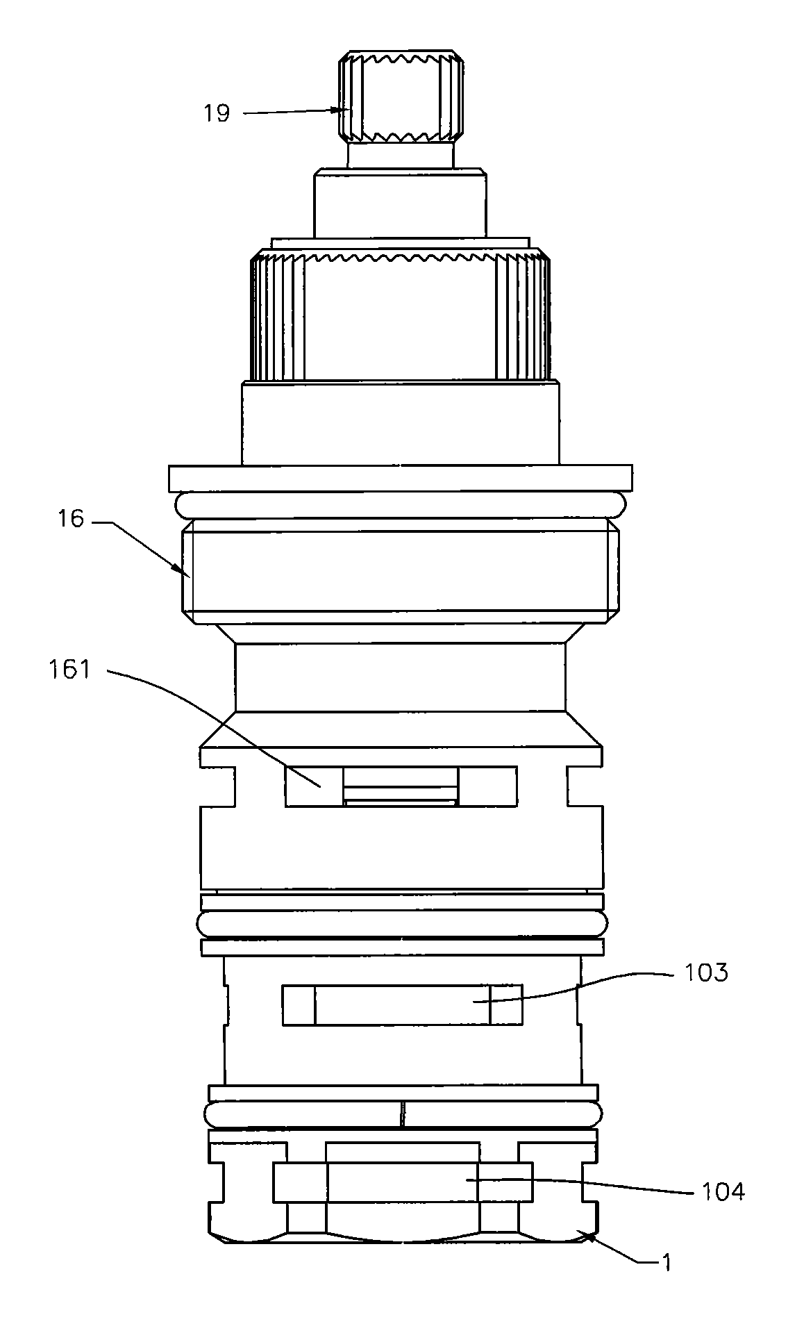
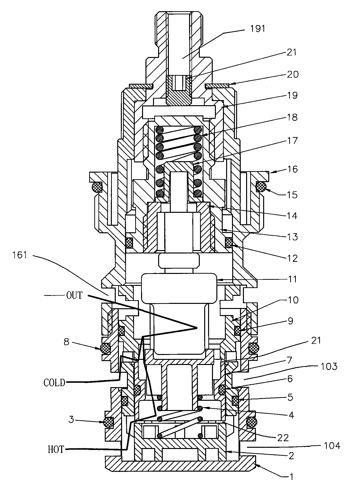
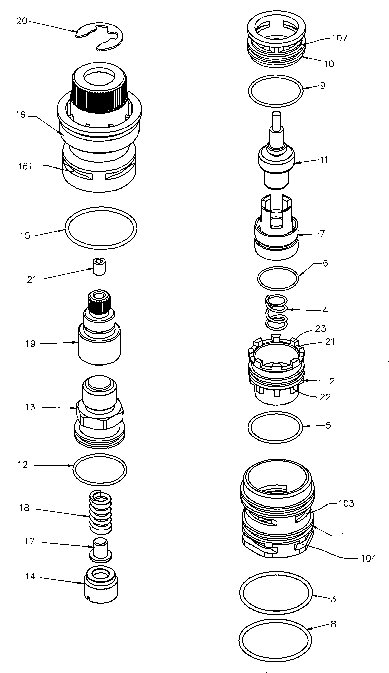
[0014] combine figure 2 and image 3 As shown, the valve core of the constant temperature and pressure water nozzle provided in this embodiment includes: a lower valve sleeve 1, a first sealing ring 3, a second sealing ring 8, a water diversion member 2, a third sealing ring 5, a return spring 4, an adjustment Device 7, fourth seal ring 6, compression seal 10, fifth seal ring 9, heat sensitive element 11, set screw 14, top cap 17, buffer spring 18, sixth seal ring 12, screw rod 13, valve stem 19. Temperature regulating valve sleeve 16, seventh sealing ring 15, collar 20 and temperature limiting adjusting screw 21.

[0015] combined reference figure 2 and image 3 , the outer edge of the temperature regulating valve sleeve 16 is provided with a seventh sealing ring 15, the lower part of the temperature regulating valve sleeve 16 is provided with a water outlet 161, and the lower port is provided with an internal thread. The upper end of the lower valve sleeve 1 is corresp...


PUM


Abstract

The invention relates to a nozzle valve core with constant temperature and pressure, comprising a valve sleeve, and a temperature regulating assembly, a thermal sensitive element, a regulator and a return spring cooperatively arranged in the internal chamber of the valve sleeve from top to bottom, and further comprising a water separating element and a compressing sealing element sleeved in the internal chamber of the valve sleeve. A water outlet, a cold water inlet and a hot water inlet are arranged at different heights of the side wall of the valve sleeve from top to bottom; the water separating element is matched with the cold water inlet and hot water inlet to confine a cold water pathway and a hot water pathway and provide a cold water control opening and a hot water control opening respectively matching with the cold water pathway and the hot water pathway; the compressing sealing element is sealed with the inner wall of the valve sleeve and compresses the water separating element in the valve sleeve; and the regulator floats between the cold water control opening and hot water control opening under the action of the thermal sensitive element and the return spring. The invention forms a zigzag water inlet pathway to remarkably balance water inlet pressure while ensuring constant temperature, and also has the advantages of simple structure, safety and reliability.

Description

technical field [0001] The invention relates to the technical field of plumbing equipment, in particular to a constant temperature and pressure balancing valve core. Background technique [0002] With the advancement of science and technology and the improvement of living standards, valve cores with constant temperature functions have been widely used in various bathing water supply systems such as homes and hotels. After setting, the mixed outlet water temperature is constant, which can avoid the problem of hot and cold outlet water temperature caused by the change of inlet water pressure and temperature instability of ordinary valve cores, and is safe and anti-scald. [0003] The key point to effectively control the constant outlet water temperature is to sense the real and effective outlet water temperature, and to be able to sensitively adjust the ratio of hot and cold inlet water. The sensing of the true and effective outlet water temperature means that the hot and col...

Claims


Application Information

Patent Timeline
Patent Type & Authority Patents(China)
IPC IPC(8): F16K31/64F16K11/00F16K47/00
CPCG05D23/1346
Inventor 谢庆俊
Owner 谢庆俊
Learn More