
Image display device and electronic apparatus

A technology for an image display device and a display area, which can be applied to projection devices, image reproducers using projection devices, static indicators, etc., and can solve problems such as damage to display quality.

Active Publication Date: 2009-08-05
SEIKO EPSON CORP
View PDF3 Cites 3 Cited by
  • Summary
  • Abstract
  • Description
  • Claims
  • Application Information

AI Technical Summary

Problems solved by technology

[0004] However, when PWM control is performed on the light source, the bright part and dark part of the horizontally extending strip appear to move at a slow speed above or below the screen (moving noise: scroll noise), which greatly damages the display quality. The problem

Method used


Image

  • Image display device and electronic apparatus
  • Image display device and electronic apparatus
  • Image display device and electronic apparatus

Examples


Embodiment Construction

[0018] Hereinafter, embodiments of the present invention will be described with reference to the drawings.

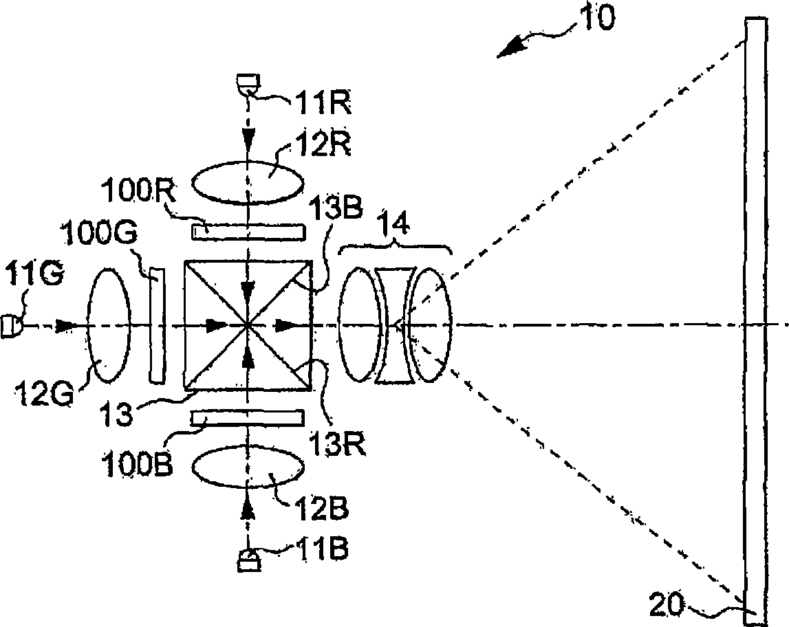
[0019] figure 1 It is a plan view showing the optical configuration of a projector using the image display device according to the embodiment of the present invention.

[0020] In this figure, LED11R is an example of a solid-state light source, is a light-emitting diode emitting R (red) color light, and is located at 12 o'clock when viewed from the center of a dichroic prism (dichroic prism) 13 . The collimator lens 12R collimates the R light emitted from the LED 11R to enter the display panel 100R. In this embodiment, the display panel 100R is a transmissive liquid crystal panel, has a plurality of pixels, and changes the transmittance for each pixel. For this reason, the emitted light of the display panel 100R serves as a portion representing an image of the R color component.

[0021] Similarly, LEDs 11G and 11B are light-emitting diodes that emit G (green) and B ...


PUM


Abstract

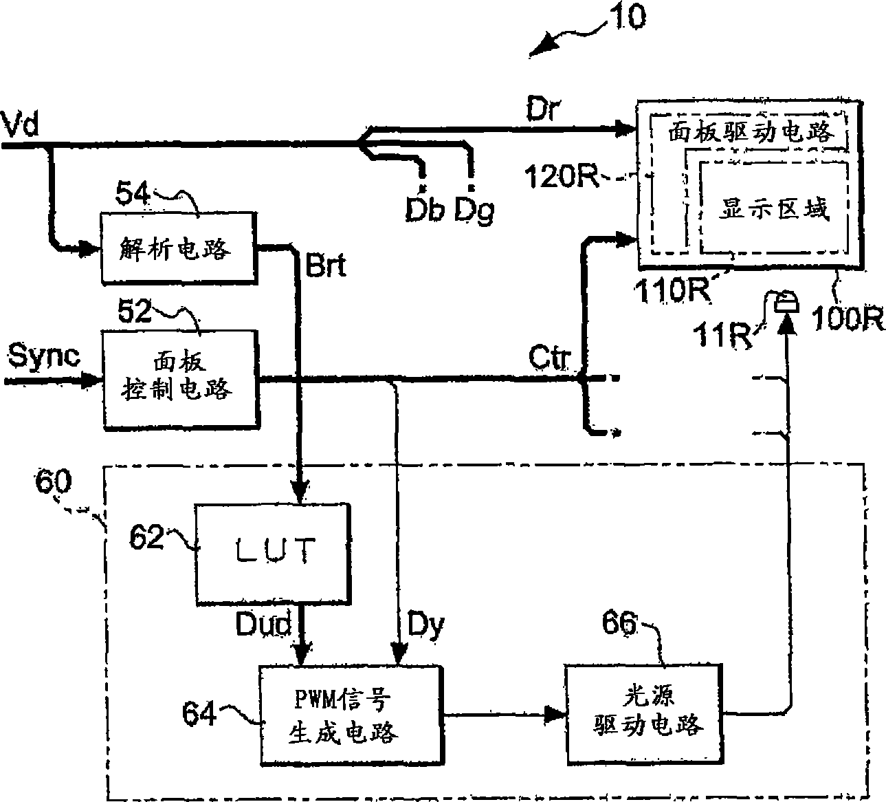
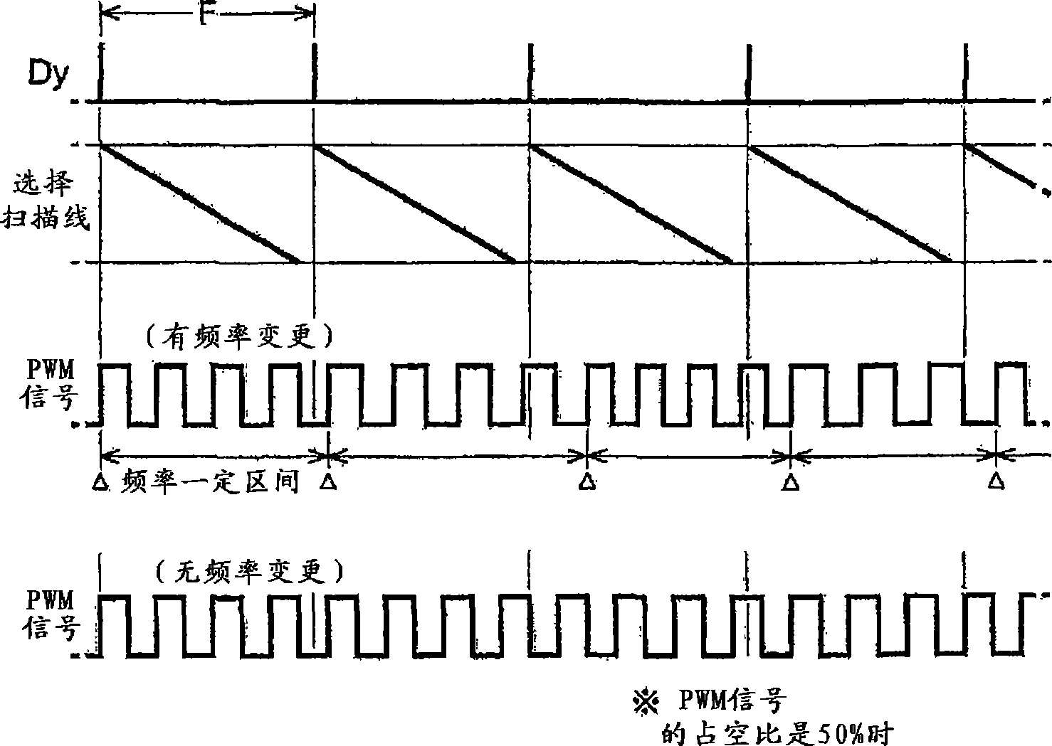
The invention provides an image display device and an electronic apparatus that are capable of reducing the occurrence of scroll noise in the case of performing PWM control of a light source. An LED (11R) emits red (R) light. A display area (110R) of the display panel changes the transmission rate of the R light irradiated by the LED (11R) according to each pixel. A panel driving part (120R) drives the display area (110R) based on the display data (Dr) of the transmission rate in the display area (110R) prescribed by each pixel. A PWM signal generation circuit (64) generates a PWM signal for driving each LED, based on teh ratio denoted by the data (Dud). The frequency of the PWM signal is not defined, but changed in a pre-determined range. A light source driving circuit (66) drives the LED (11R) based on the PWM signal.

Description

technical field [0001] The invention relates to a technique for improving display unevenness when pulse width modulation is performed on a light source to control luminous brightness. Background technique [0002] For light sources such as LD (Laser Diode) and LED (Light Emitting Diode), it is easy to adjust the brightness of light emission through PWM (Pulse Width Modulation) control. The reason is that the use of PWM is favorable in terms of being able to construct a digital circuit, light quantity, stability of the circuit, and the like, and is favored in the above-mentioned points. There is a proposal to use such a light source in a projector, for example, to suppress color change and expand the apparent dynamic range at the time of display (see Patent Document 1). [0003] Patent Document 1: JP-A-2004-354717 [0004] However, when PWM control is performed on the light source, the bright part and dark part of the horizontally extending strip appear to move at a slow sp...

Claims


Application Information

Patent Timeline
Patent Type & Authority Applications(China)
IPC IPC(8): G09G3/34H04N9/31
CPCG09G2320/0233G09G2320/064G09G3/3406G09G3/34G09G3/02G03B21/00
Inventor 丰冈隆史
Owner SEIKO EPSON CORP
Learn More