
De-airing hydraulic tensioner

A hydraulic tensioner and degassing technology, which is applied to belts/chains/gears, mechanical equipment, transmissions, etc., can solve problems such as rattling, and achieve the effect of suppressing rattling noise

Inactive Publication Date: 2008-04-16
TSUBAKIMOTO CHAIN CO
View PDF1 Cites 0 Cited by
  • Summary
  • Abstract
  • Description
  • Claims
  • Application Information

AI Technical Summary

Problems solved by technology

[0008] In view of this, the purpose of the present invention is to solve the above-mentioned problems existing in the existing hydraulic tensioner, and to provide a degassing type hydraulic tensioner equipped with a degassing valve assembly of a new structure, which can When the engine is started, the travel chain is suppressed due to the influence of air mixed in the high-pressure oil chamber, and the air that enters the main body during engine operation can be discharged smoothly to maintain a high-pressure state in the high-pressure oil chamber.

Method used


Image

  • De-airing hydraulic tensioner
  • De-airing hydraulic tensioner
  • De-airing hydraulic tensioner

Examples


Embodiment 1

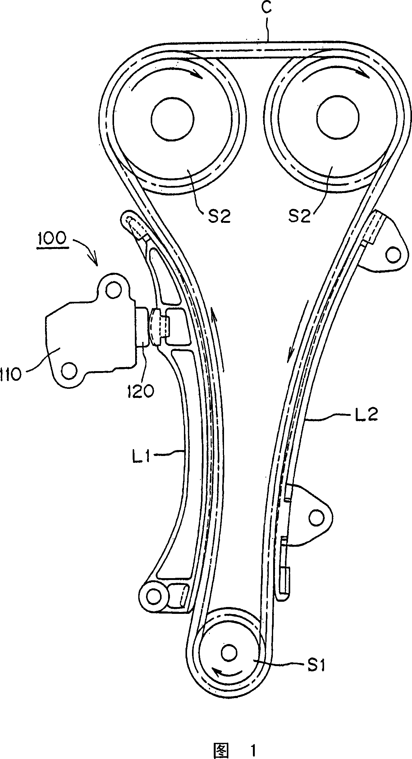
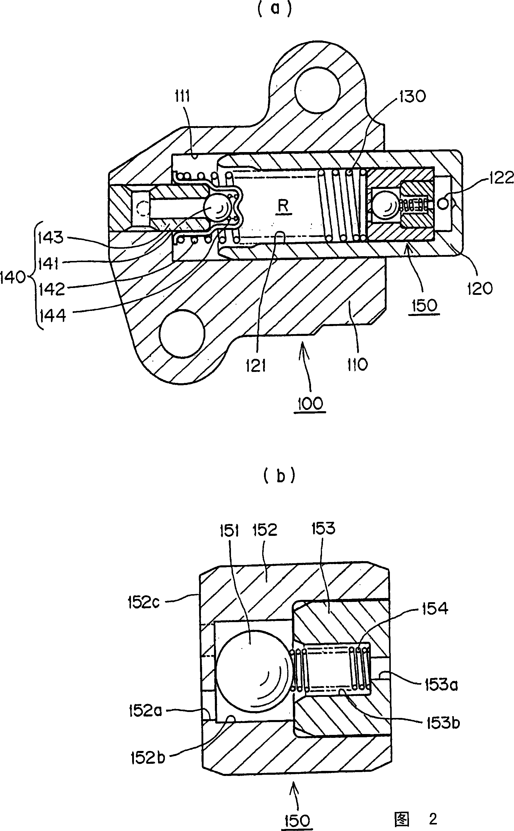
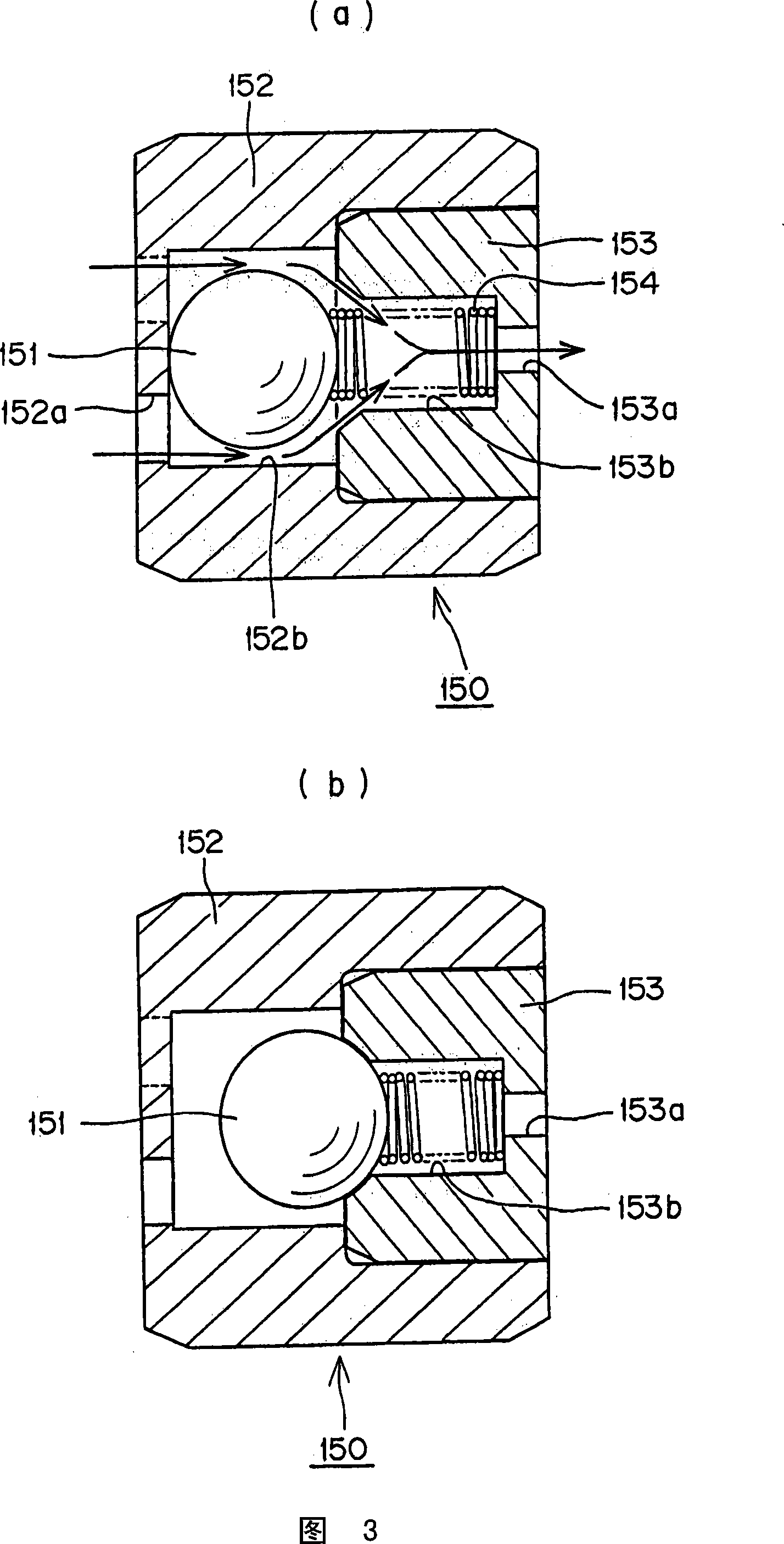
[0021] The degassing type hydraulic tensioner of Example 1 which is one embodiment of the present invention will be described with reference to FIGS. 1 to 3 . Fig. 1 is a diagram of the use status of the degassed hydraulic tensioner of Embodiment 1 of the present invention, Fig. 2 (a) is a sectional view of the degassed hydraulic tensioner 100 shown in Fig. 1, and Fig. 2 (b) is a diagram of Fig. An enlarged view of the one-way ball valve assembly for air relief, designated by reference numeral 150 in (a). Figure 3(a) is a drawing illustrating the exhaust state of the one-way ball valve assembly for air release shown in Figure 2(b), that is, the valve opening state, and Figure 3(b) is illustrating the valve closing state Attached picture.

[0022] First, as shown in FIG. 1 , the degassed hydraulic tensioner 100 according to Embodiment 1 of the present invention is installed on the main body of the engine on the slack side of the timing chain C, and the timing chain C is hung a...

Embodiment 2

[0035] The degassing type hydraulic tensioner of Example 2 which is another embodiment of the present invention will be described with reference to FIG. 4 .

[0036] Figure 4(a) shows the degassing type hydraulic tensioner 200 of this embodiment, its plunger 220 is slidably inserted into the plunger sliding hole 211 formed on the main body 210, and the high-pressure oil chamber R is in the plunger The slide hole 211 is formed between the plunger inner hole 221 formed in the plunger 220 , and the high-pressure oil chamber R accommodates a plunger urging mechanism 230 composed of a coil spring biasing the plunger 220 in a direction to protrude.

[0037] In addition, at the bottom of the plunger sliding hole 211, a one-way valve assembly 240 is installed to allow hydraulic oil to flow into the high-pressure oil chamber R formed between the plunger sliding hole 211 and the plunger inner hole 211 and prevent it from flowing backward. .

[0038] The one-way valve assembly 240 is an...


PUM


Abstract

The invention provides a desaeration type hydraulic tensioner which can restrain a chain from shaking due to the influence of mixed air inside a high pressure oil chamber, and discharge the air mixed into the main body smoothly so as to remain the high pressure oil chamber in a high pressure state. The tensioner is provided with a single-way ball valve assembly (150) which is used for discharging the air. The single-way ball valve assembly comprises a single-way ball valve (151) which is used for preventing the hydraulic oil inside the high pressure oil chamber from flowing out and discharging the mixed air; a holding device (152) which is used for holding the single-way ball valve internally and driving the single-way ball valve to move; a column ball seat (153) which is embedded and fixed at the air discharge side of the front end of the holding device, preventing the hydraulic oil inside the high pressure oil chamber from flowing out through the seat of the single-way ball valve, and being provided with a vent (153a) which is communicated with the external part of the main body or a plunger piston; and a valve ball spring which is arranged inside the hollow part of the column ball seat and positioned between the single-way ball valve and the vent so as to stress a force on the single-way ball valve.

Description

technical field [0001] The present invention relates to a hydraulic tensioner for applying appropriate tension to, for example, a timing belt or a timing chain of a vehicle engine. Background technique [0002] In general, for the timing belt and the timing chain that transmit rotation between the crankshaft and the camshaft of the vehicle engine, a hydraulic tensioner having a one-way ball valve mechanism that prevents the hydraulic oil in the high-pressure oil chamber from flowing backward is widely used. . [0003] In the past, as such a hydraulic tensioner having a one-way ball valve mechanism, a hydraulic tensioner 500 shown in FIG. A cylindrical plunger 520 protruding freely from the chain; a post provided between the plunger sliding hole 511 and the plunger inner hole 521 formed in the plunger, and urging the plunger 520 in a direction to protrude Plug force mechanism 530; a one-way valve installed at the bottom of the plunger sliding hole 511 to allow hydraulic oil...

Claims


Application Information

Patent Timeline
Patent Type & Authority Applications(China)
IPC IPC(8): F16H7/08
CPCF16H2007/0817F16H2007/0859F16H7/0836F16H7/0848F16H2007/0806F16H7/08
Inventor 浪江勤桥本裕至
Owner TSUBAKIMOTO CHAIN CO
Learn More