Transparent solar cell module

A solar cell, transparent technology, applied in circuits, photovoltaic power generation, electrical components, etc., can solve the problems of increased power generation cost, increased manufacturing cost, increased laser manufacturing process, etc., to achieve the effect of improving the glare problem

Active Publication Date: 2010-08-25
IND TECH RES INST
View PDF5 Cites 0 Cited by
  • Summary
  • Abstract
  • Description
  • Claims
  • Application Information

AI Technical Summary

Problems solved by technology

[0011] On the other hand, although the see-through type product can increase the transmittance by 10%, it will sacrifice 30% of the efficiency, resulting in an increase of its power generation cost per watt by about 4%
In addition, light-trans

Method used


Image

  • Transparent solar cell module
  • Transparent solar cell module

Examples


Embodiment 1

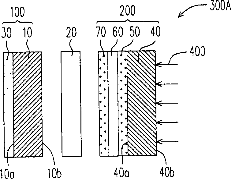
[0049] FIG. 1 is a schematic cross-sectional view of a transparent solar cell module according to a first embodiment of the present invention.

[0050] Please refer to FIG. 1, a transparent solar cell module 300A includes an optically transparent substrate 100 and a transparent solar cell 200, and an insulating layer 20 is sandwiched between the transparent solar cell 200 and the optically transparent substrate 100. expressed as a distance apart.

[0051]The transparent solar cell 200 includes a transparent substrate 40 , an electrode 50 , an electrode 70 and a photoelectric conversion layer 60 . The electrode 50 of the transparent solar cell 200 is located on the first surface 40 a of the transparent substrate 40 . The photoelectric conversion layer 60 is sandwiched between the electrode 50 and the electrode 70 . The optically transparent substrate 100 includes an optical filter film 30 and a transparent substrate 10 . The insulating layer 20 is located between the second ...

Embodiment 2

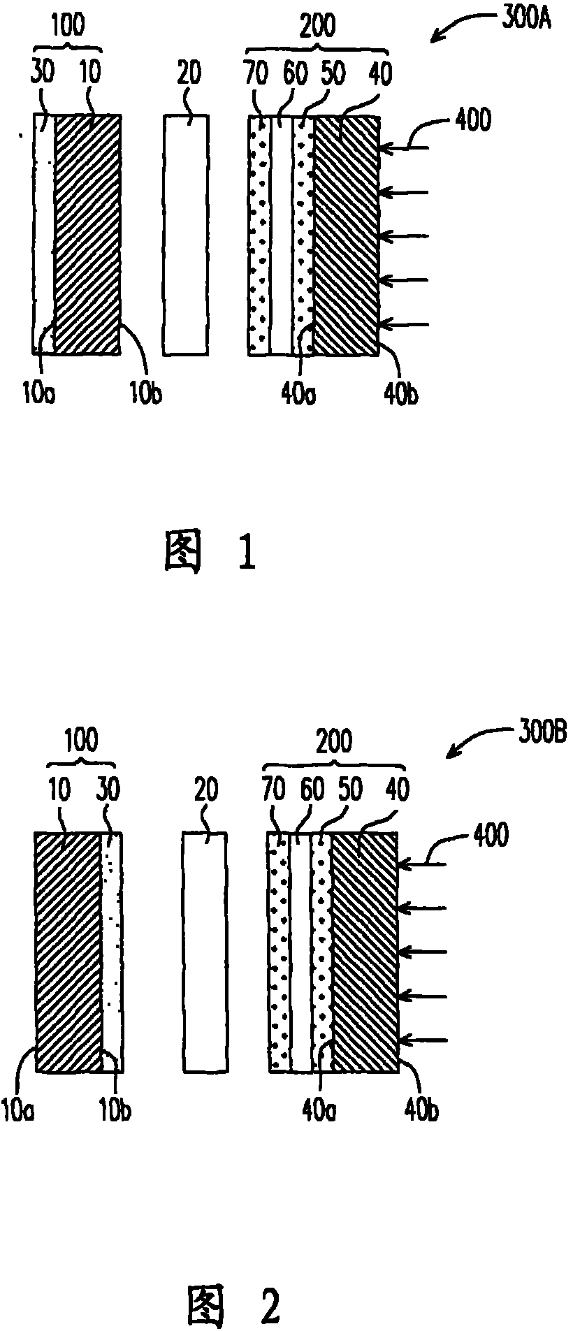
[0055] FIG. 2 is a schematic cross-sectional view of a transparent solar cell module according to a second embodiment of the present invention.

[0056] Please refer to FIG. 2, a transparent solar cell module 300B includes an optically transparent substrate 100 and a transparent solar cell 200, and an insulating layer 20 is sandwiched between the transparent solar cell 200 and the optically transparent substrate 100. expressed as a distance apart.

[0057] The transparent solar cell 200 includes a transparent substrate 40 , an electrode 50 , an electrode 70 and a photoelectric conversion layer 60 . The electrode 50 of the transparent solar cell 200 is located on the first surface 40 a of the transparent substrate 40 . The photoelectric conversion layer 60 is sandwiched between the electrode 50 and the electrode 70 . The optically transparent substrate 100 includes an optical filter film 30 and a transparent substrate 10 . The optical filter film 30 is located on the second ...


PUM


Abstract

A transparent-typed solar cell module includes a transparent-typed solar cell and a transparent optical substrate. The transparent optical substrate comprises an optical filter and a first transparent substrate. The transparent-typed solar cell includes a first electrode, a photoelectric conversion layer, a second electrode and a second transparent substrate in sequence.

Description

【Technical field】 [0001] The invention relates to a transparent solar cell module. 【Background technique】 [0002] Solar energy is an inexhaustible and non-polluting energy source. It has always been the focus of attention when solving the pollution and shortage problems faced by current petrochemical energy sources. Therefore, if buildings can integrate solar cells (building integrated photovoltaic, BIPV) is undoubtedly a hot research topic in the future. [0003] Early solar cells were installed on the roof, but in narrow and densely populated cities, the area of ​​the top floor is limited and the installation area is not large. However, glass curtain walls on building facades have a large area and are not restricted by government regulations. Transparent solar cells can be directly integrated into glass curtains and applied in buildings, which is beneficial. This will be an area where transparent solar cell modules can be developed. [0004] Solar cells combined with a...

Claims


Application Information

Patent Timeline
IPC IPC(8): H01L31/0232H01M14/00H01L31/042H01L51/42H01G9/20H01L51/44H01L31/054
CPCY02E10/50Y02E10/549
Inventor 翁得期詹逸民郭昭显
Owner IND TECH RES INST
Why Eureka
Try Eureka