Ventilating device

A ventilation device and air technology, applied in the direction of climate sustainability, ventilation system, heating method, etc., can solve problems such as space constraints for ventilation devices

Inactive Publication Date: 2012-05-30
DAIKIN IND LTD
View PDF1 Cites 0 Cited by
  • Summary
  • Abstract
  • Description
  • Claims
  • Application Information

AI Technical Summary

Problems solved by technology

For this reason, it is necessary to sufficiently ensure the installation space of the air duct, so that the installation place of the ventilation device is restricted.

Method used


Image

  • Ventilating device
  • Ventilating device
  • Ventilating device

Examples


Embodiment Construction

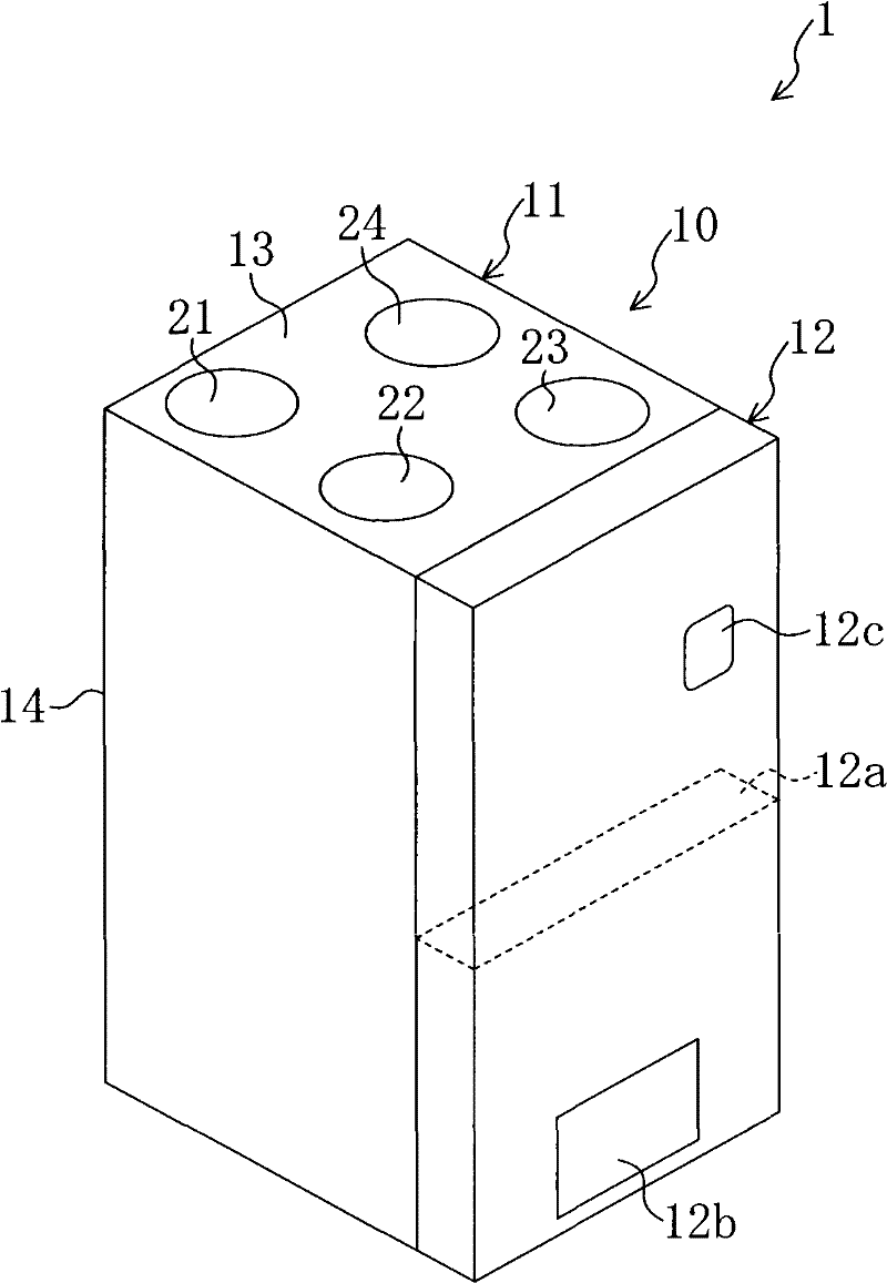
[0089] Hereinafter, embodiments of the present invention will be described in detail with reference to the drawings. In addition, the terms "right", "left", "upper", "lower", "front", and "rear" used in the following descriptions mean figure 1 status shown.

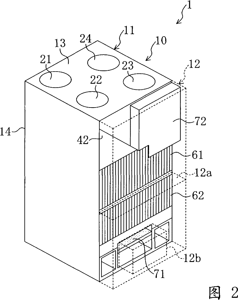
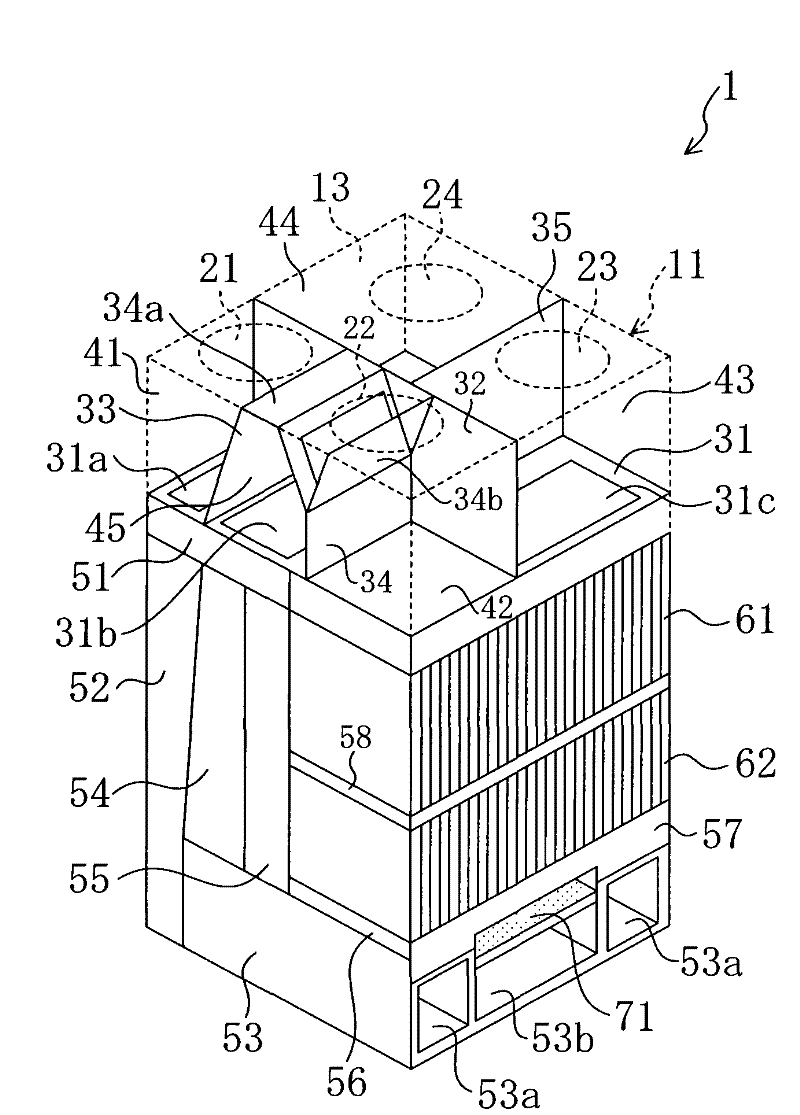
[0090] First, while referring to Figure 1 to Figure 9 , the configuration of the ventilator 1 according to the present embodiment will be described. The ventilator 1 of the present embodiment constitutes a so-called floor-standing ventilator installed on the floor of a room. Such as figure 1 and figure 2 As shown, the ventilator 1 has a housing 10 formed in the shape of an elongated cuboid. The housing 10 has a housing main body 11 with an open front, and a front panel 12 that is detachably attached to the front opening of the housing main body 11 .

[0091] An upper panel 13 is formed on the upper portion of the housing main body 11 , and a rear panel 14 is formed on the rear side of the housing main body 11 . A...


PUM


Abstract

The invention discloses a ventilator. An outdoor air suction port (21), an indoor air suction port (22), an indoor air supply port (23) and an outdoor exhaust port (24) are formed on an upper plate (13) of a casing (10), and a duct is permitted to be connected to each of the air suction ports (21, 22) and the air supply / exhaust ports (23, 24).

Description

technical field [0001] The present invention relates to a ventilator including a heat exchanging element for exchanging heat with each air while supplying outdoor air to a room and exhausting the room air to the outside. Background technique [0002] Conventionally, for example, as disclosed in Patent Document 1, a ventilator including a heat exchange element is known. The ventilator supplies outside air to the room and exhausts the room air to the outside. At this time, the outdoor air sent indoors and the indoor air discharged outdoors pass through the heat exchange element. The heat exchanging elements constitute a straight-through heat exchanger in which the passage directions of the air are perpendicular to each other. And, in the heat exchange element, heat exchange is performed between outdoor air and indoor air. Also, in the heat exchange element, moisture is exchanged between the outdoor air and the indoor air. [0003] In addition, the ventilator in patent docu...

Claims


Application Information

Patent Timeline
Patent Type & Authority Patents(China)
IPC IPC(8): F24F7/08
CPCY02B30/16F24F12/006Y02B30/563F24F2012/007Y02B30/56F24F7/08F24F13/20F24F13/28
Inventor 松木义孝西田隆彦奥村恭伸武内伸胜
Owner DAIKIN IND LTD
Why Eureka
Try Eureka