

Microwave processing apparatus
A microwave processing and microwave technology, which is applied in the field of microwave processing devices, can solve problems such as inability to uniformly heat objects, and achieve the effects of reducing calorific value and preventing damage and failure
- Summary
- Abstract
- Description
- Claims
- Application Information
AI Technical Summary
Problems solved by technology
Method used
Image

Examples
no. 1 approach
[0068] (1-1) Structure and working overview of microwave oven
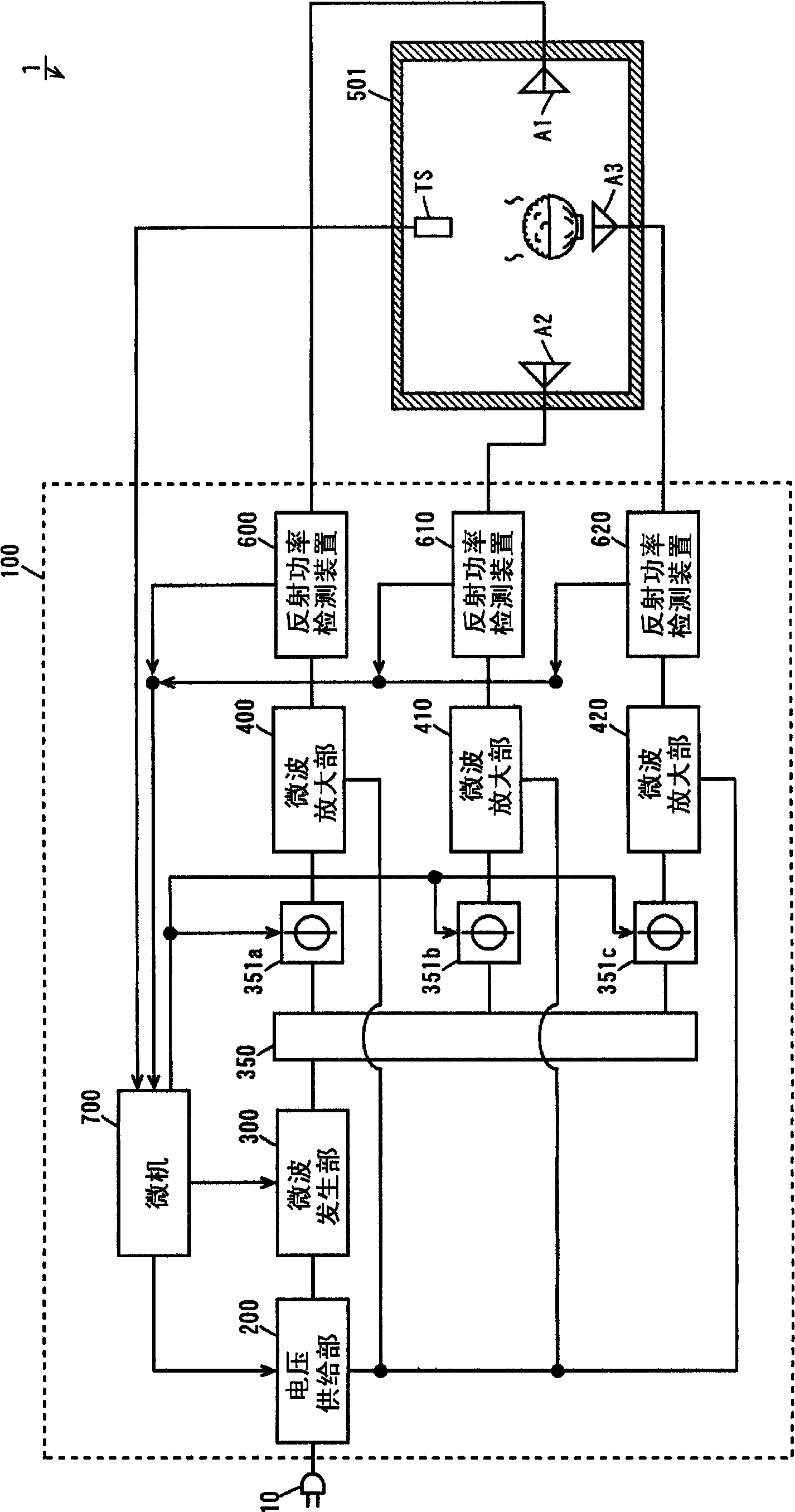
[0069] figure 1 It is a block diagram showing the structure of the microwave oven of 1st Embodiment. Such as figure 1 As shown, the microwave oven 1 of this embodiment includes a microwave generator 100 and a casing 501 . Three antennas A1 , A2 , A3 are arranged in the casing 501 .
[0070] In the present embodiment, two of the three antennas A1 , A2 , A3 in the casing 501 are arranged so as to face each other in the horizontal direction.
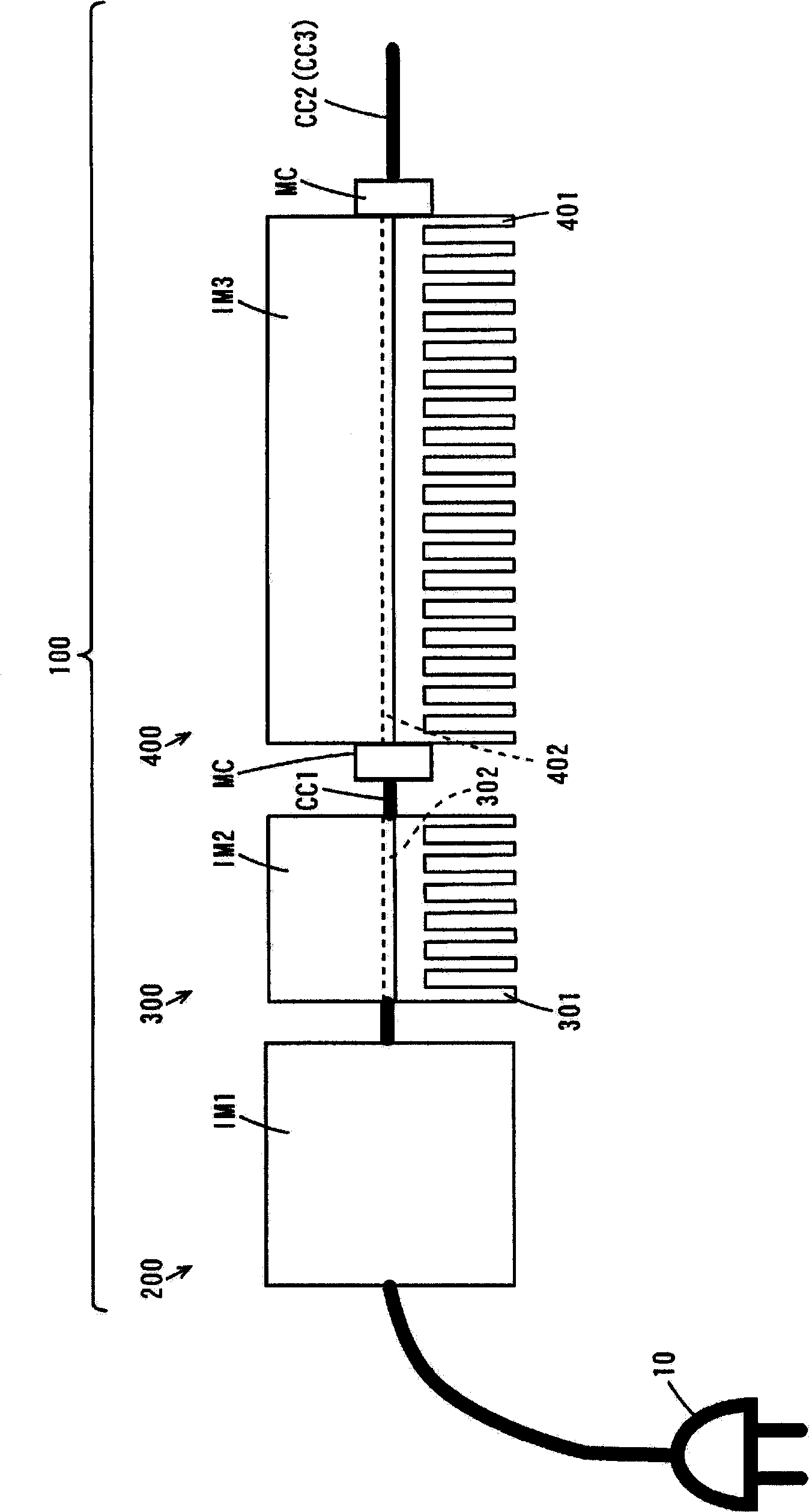
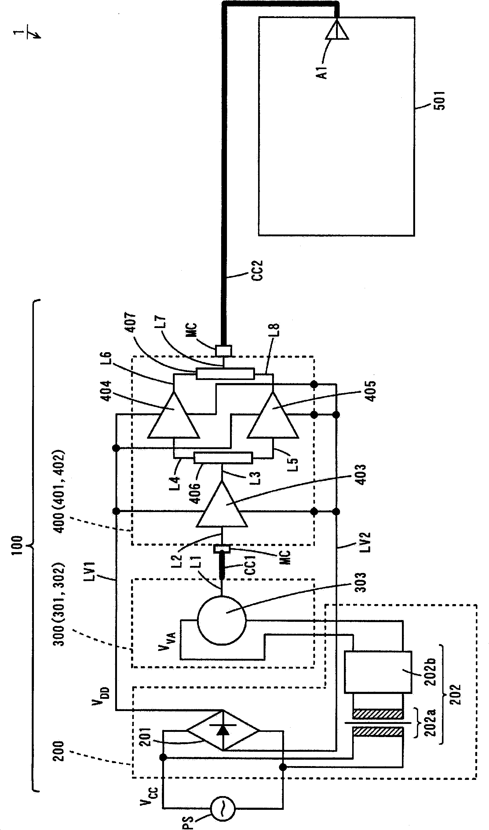
[0071] The microwave generating device 100 includes: a voltage supply part 200; a microwave generating part 300; a power divider 350; three phase converters 351a, 351b, 351c having the same structure; three microwave amplifying parts 400, 410, 420 having the same structure; Three reflected power detection devices 600 , 610 , 620 having the same structure; and a microcomputer 700 . The microwave generating device 100 is connected to an industrial power supply through a powe...
no. 2 approach
[0225] The microwave oven of the second embodiment is different from the microwave oven 1 of the first embodiment in the following points.
[0226] (2-1) Structure and working overview of microwave oven
[0227] Figure 13 It is a block diagram showing the structure of the microwave oven of 2nd Embodiment. Such as Figure 13 As shown, the structure of the microwave generator 100 of the microwave oven 1 of the second embodiment is different from that of the microwave oven 1 of the first embodiment ( figure 1 ).
[0228] In the microwave oven 1 of the present embodiment, the microwave generating device 100 includes: a voltage supply part 200; two microwave generating parts 300, 310 having the same structure; a power divider 360; two phase changers 351a, 351b having the same structure; Three microwave amplifiers 400 , 410 , 420 with the same structure; three reflected power detection devices 600 , 610 , 620 with the same structure; and the microcomputer 700 .
[0229] Here, ...
no. 3 approach
[0242] The microwave oven of the third embodiment is different from the microwave oven 1 of the first embodiment in the following points.
[0243] (3-1) Structure and working overview of microwave oven
[0244] Figure 14 It is a block diagram showing the structure of the microwave oven of 3rd Embodiment. Such as Figure 14 As shown, the structure of the microwave generator 100 of the microwave oven 1 of the third embodiment is different from that of the microwave oven 1 of the first embodiment ( figure 1 ).
[0245] In the microwave oven 1 of the present embodiment, the microwave generating device 100 includes: a voltage supply part 200; a microwave generating part 300; three power dividers 350A, 350B, 350C having the same structure; four phase changers 351a, 351b having the same structure , 351c, 351d; four microwave amplifiers 400, 410, 420, 430 with the same structure; four reflected power detection devices 600, 610, 620, 630 with the same structure; and the microcompu...
PUM
 Abstract
Description
Claims
Application Information