Microwave feeding source of ultra-high performance antenna

An ultra-high-performance, antenna technology, applied to antennas, waveguide horns, electrical components, etc., can solve the problem of poor antenna standing wave ratio and cross polarization performance, troublesome processing of feed curved waveguide, and damage to the circular symmetry of the feed pattern In order to achieve high cross-polarization discrimination rate, reduce processing difficulty, and realize the effect of cross-polarization discrimination rate

Inactive Publication Date: 2009-03-11
GUANGDONG SHENGLU TELECOMM TECH
View PDF0 Cites 19 Cited by
  • Summary
  • Abstract
  • Description
  • Claims
  • Application Information

AI Technical Summary

Problems solved by technology

The disadvantage is that the feeding bending waveguide processing technology is cumbersome, the cost is high, and the consistency is not good; especially due to the existence of the bending waveguide, the circular symmetry of the feed source pattern is destroyed, which has played a role in the standing wave ratio and cross polarization performance of the antenna. Bad effect; and because this kind of feed pattern is not easy to change, in order to meet the requirements of ultra-high-performance antennas, it is necessary to install a high metal surround on the edge of the antenna aperture and line it with absorbing materials. Therefore, seeking A feed solution with better electrical performance and lower cost than the curved waveguide feed has always been people's dream

Method used


Image

  • Microwave feeding source of ultra-high performance antenna
  • Microwave feeding source of ultra-high performance antenna
  • Microwave feeding source of ultra-high performance antenna

Examples


Embodiment Construction

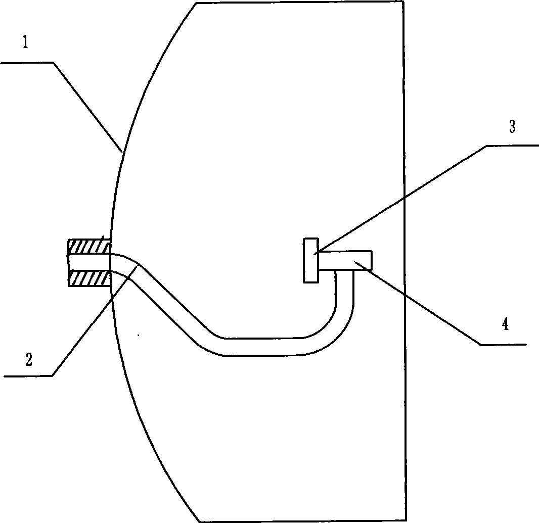
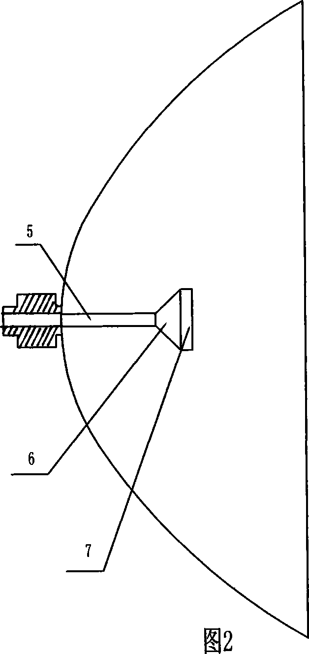
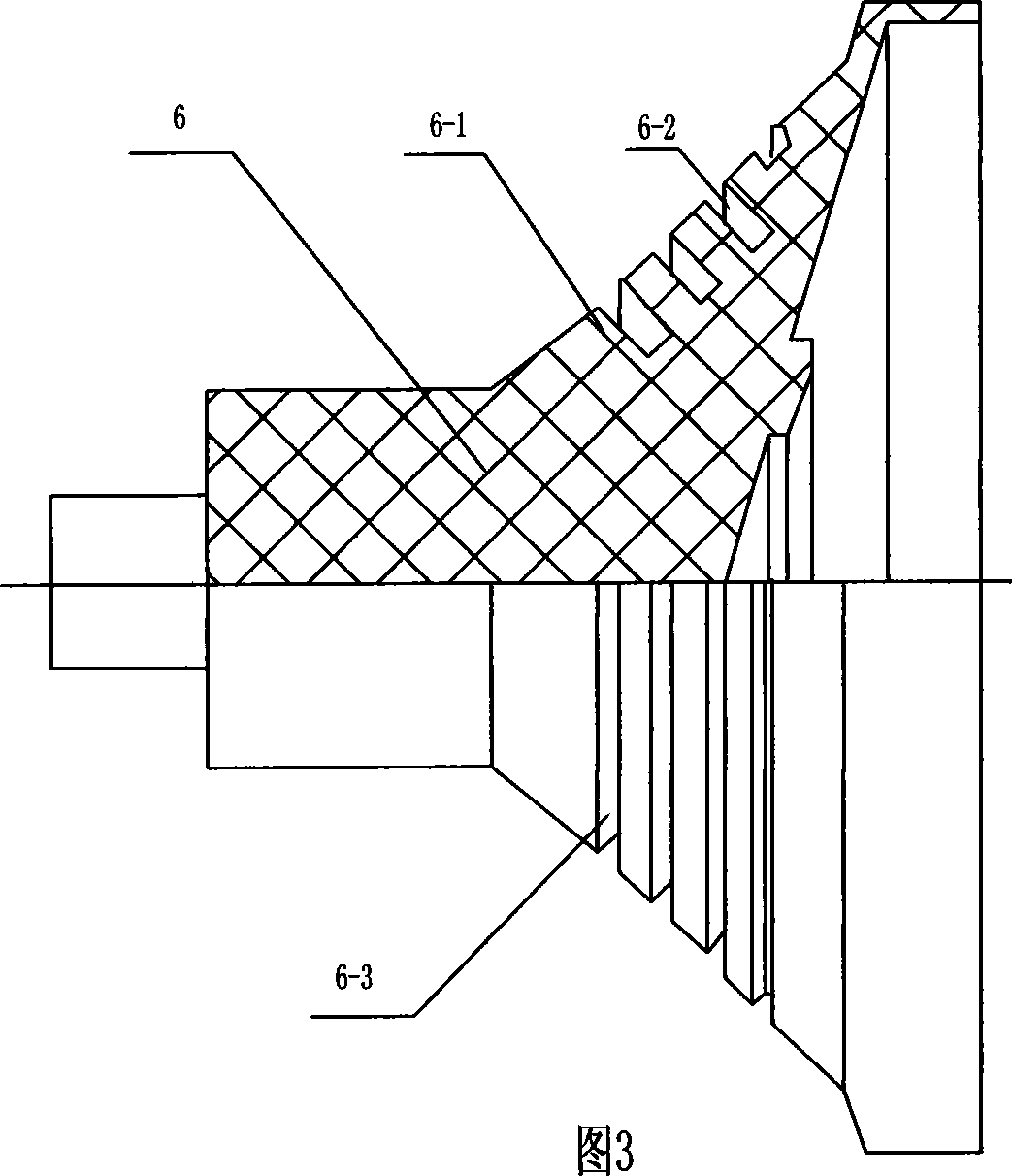
[0021] As shown in Figure 2, the present invention is a microwave feed source for an ultra-high-performance antenna, including a metal circular waveguide 5, a dielectric support 6 and a metal secondary reflector 7 connected to each other and on the same axis. The waveguide 5, the dielectric support 6 and the metal sub-reflector 7 are all circularly symmetrical. The three parts are all precision-processed on a CNC lathe and assembled in order by tight crimping and fitting. The input end of the circular waveguide 5 is compared with the standing wave A small circular / rectangular transition is used for measuring or connecting microwave equipment. A complete set of ultra-high performance antenna can be formed by installing a flange matching the size of the main reflector of the antenna at the appropriate position of the circular waveguide 5. Figure 6 and Figure 7 It is the measured far-field pattern when the above-mentioned feed is installed on a 0.3M parabolic antenna. The diel...


PUM


Abstract

The invention discloses a feedback type round wave-guide feed source for a microwave antenna, which comprises a round wave-guide, a taper medium support and a subreflector. The three parts are positioned on a same axial line, and tight compression-joint cooperation is adopted between the round wave-guide and the medium support and between the medium support and the subreflector. The feedback type round wave-guide feed source is characterized in that the parts are on the same axial line after being assembled; a plurality of annular grooves are processed at certain positions on the conical surface of a taper medium connecting block and a taper of the metal subreflector. Through the annular grooves processed on the subreflector and the conical surface of medium support, the invention changes the transmission direction of part reflected wave and reduces the electromagnetic energy entering the inside of a round wave-guide opening, thereby improving the standing wave ratio index of the feed source and having no influence on other indexes. The feed source with the structure has high rate of finished product for the production and processing, low cost and favorable generalizing value.

Description

technical field [0001] The present invention relates to the technical field of microwave antennas, in particular to a feed source structure of microwave antennas. Background technique [0002] At present, the feeding methods of microwave antennas include feed-forward, feed-back, and bias-feed, among which the feed-back antenna has been widely used because of its compact structure and high efficiency. The typical structure is a curved waveguide feed source, which consists of curved waveguide 2, The radiation cavity 3 and the radiation horn 4 are formed, and the periphery of the curved waveguide is provided with a ring-focus paraboloid 1, as shown in Fig. 1 . This kind of feed is characterized by a relatively fixed pattern, which is generally suitable for parabolic antennas with a focal-to-diameter ratio of about 0.35. The disadvantage is that the feeding bending waveguide processing technology is troublesome, the cost is high, and the consistency is not good; especially due ...

Claims


Application Information

Patent Timeline
Patent Type & Authority Applications(China)
IPC IPC(8): H01Q19/10H01Q13/02H01Q19/18
Inventor 雒建华陈志兴吕小林
Owner GUANGDONG SHENGLU TELECOMM TECH
Why Eureka
Try Eureka