Automated warehouse and method of supplying clean air to the automated warehouse

An automatic warehouse, clean air technology, applied in cleaning devices, lifting devices, conveyor objects, etc., can solve problems such as reducing storage efficiency

Inactive Publication Date: 2009-08-12
MURATA MASCH LTD
View PDF1 Cites 3 Cited by
  • Summary
  • Abstract
  • Description
  • Claims
  • Application Information

AI Technical Summary

Problems solved by technology

However, providing a space between the traveling trolley and the shelf means that storage efficiency is reduced, or the traveling trolley must be designed to be more compact

Method used


Image

  • Automated warehouse and method of supplying clean air to the automated warehouse
  • Automated warehouse and method of supplying clean air to the automated warehouse
  • Automated warehouse and method of supplying clean air to the automated warehouse

Examples


Embodiment Construction

[0046] The best embodiment for carrying out the present invention is described below.

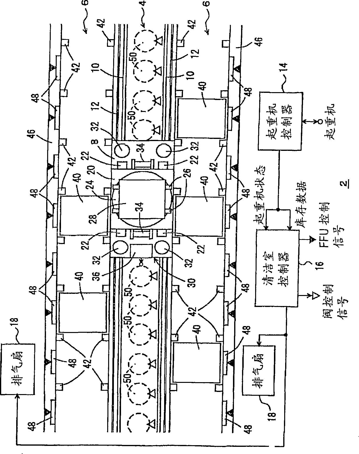
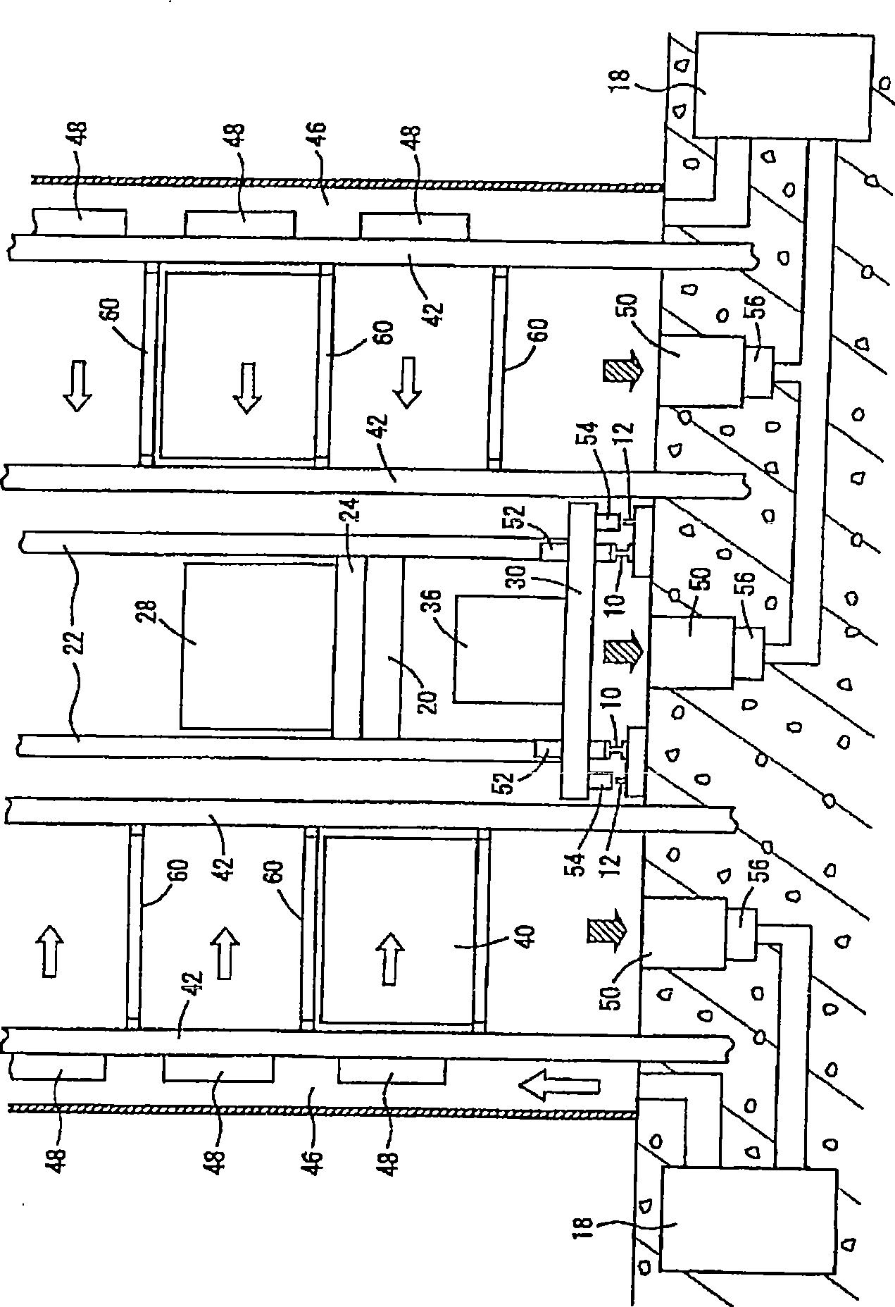
[0047] Figure 1 ~ Figure 4 The automatic warehouse 2 of an example is shown. In each figure, 4 represents a running space, and there are racks 6, 6 on its left and right sides. In addition, a part of the rack 6 may be used as a docking point for storage or egress, and processing devices such as liquid crystal substrates may be provided on the rear side of the rack 6 viewed from the travel space 4 side. The running space 4 is the access of the stacking crane 8, 10 is the running track, and 12 is the magnetic marker. Here, a pair of left and right running rails 10, 10 are used, but one rail 10 may be used. For example, a pair of magnetic markers 12 are arranged on the left and right parallel to the running rail 10 in order to enable the stacker crane 8 to always recognize its current position.

[0048] Instead of obtaining the absolute position by detecting the magnetic marker 12 , the c...


PUM


Abstract

The present invention provides an automatic warehouse and a method for supplying clean air to the automatic warehouse. The position and speed of stacker crane, and the position and speed of stacker crane are input into a clean room controller for correcting the feed amount and / or discharge amount of clean air around the stacker crane. Thereby the pollution of stored article caused by the running air current of stacker crane can be prevented.

Description

technical field [0001] The present invention relates to an automatic warehouse including stacking cranes and other transport trolleys, in particular to preventing the pollution of stored items caused by the running airflow of the transport trolleys. Background technique [0002] In the automatic warehouse of the clean room specification, there is a problem that the ambient gas near the ground that is rolled up by the transport trolley such as the stacking crane contaminates the stored goods. In an automatic warehouse, since there are racks and / or processing devices on both sides of the travel space of the stacker crane, the ambient air that is rolled up in front of the travel direction of the transport trolley flows rearward along the travel space. The ambient gas that is rolled up in the front of the traveling direction flows to the negative pressure part generated behind the traveling direction of the stacking crane, and intrudes into the surrounding racks during this proc...

Claims


Application Information

Patent Timeline
Patent Type & Authority Applications(China)
IPC IPC(8): B65G1/02B65G1/00B66F9/07
CPCB65G1/00B65G1/0407B65G1/0421B65G45/22
Inventor 林孝雄
Owner MURATA MASCH LTD
Why Eureka
Try Eureka