
Stamp insert

A technology of stamping and inserting body, applied in the direction of printing, stamping, etc., to achieve the effect of reliable assembly, strong and durable assembly

Inactive Publication Date: 2009-08-12
TRODAT GMBH
View PDF2 Cites 4 Cited by
  • Summary
  • Abstract
  • Description
  • Claims
  • Application Information

AI Technical Summary

Problems solved by technology

This has not always been proven to ensure reliable attachment of the guard to the stamp frame in all applications

Method used


Image

  • Stamp insert
  • Stamp insert
  • Stamp insert

Examples


Embodiment Construction

[0034] First of all, it should be pointed out that the same components described in different embodiments are represented by the same reference numerals and the same component names, and the disclosures made throughout the specification are applicable to the same components with the same reference numbers or the same component names. In addition, positions selected for purposes of illustration, such as top, bottom, side, etc., are relative to the figure in which they are specified, and may represent their meaning as a new position when another state is described. Individual features or combinations of features from the different embodiments shown and described can be construed as independent inventive solutions or as solutions proposed by the invention within its own right.

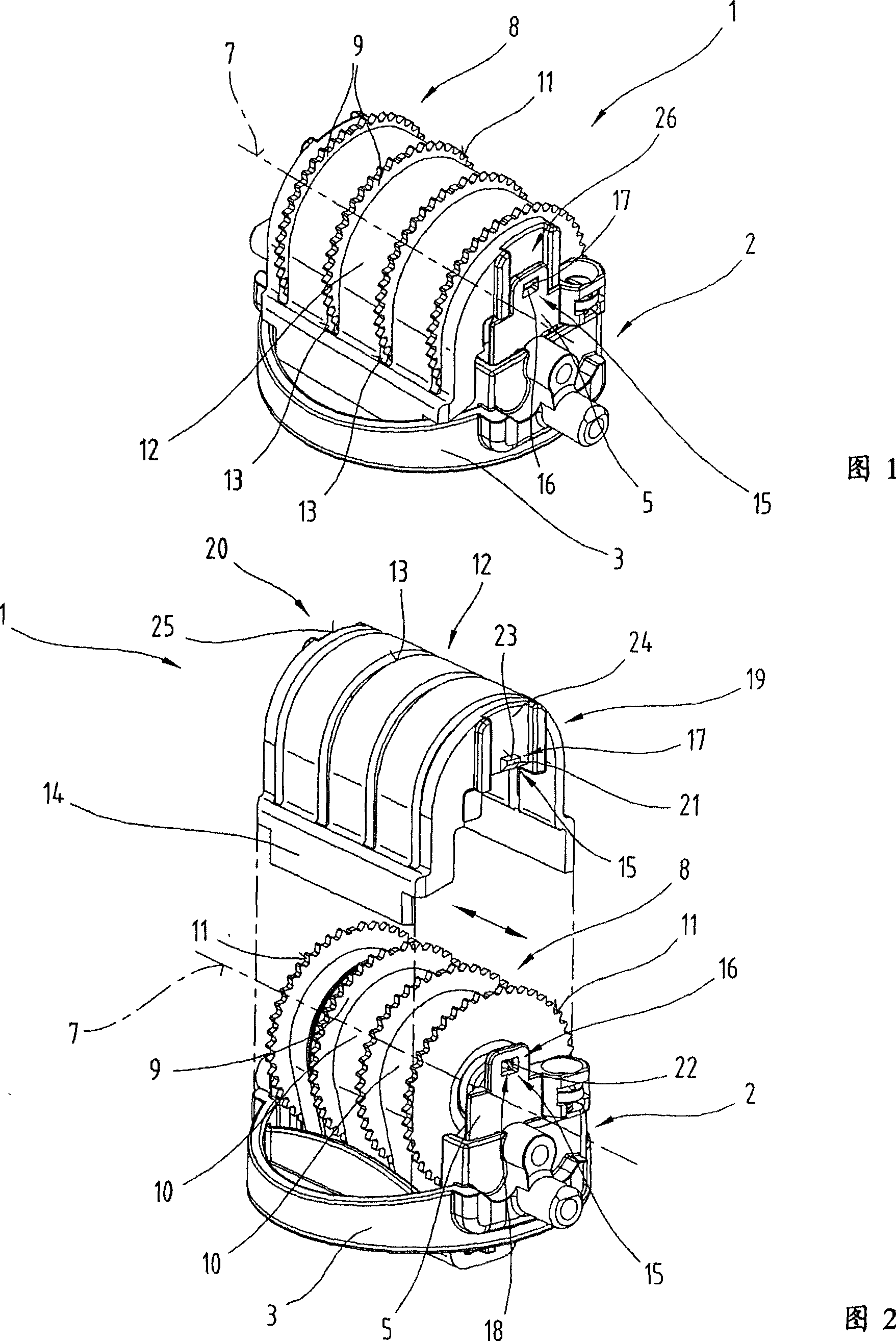
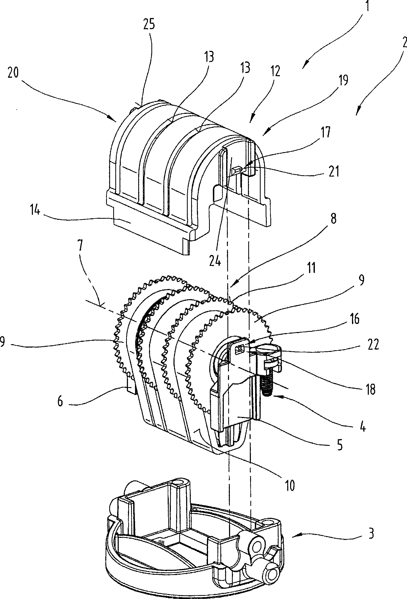
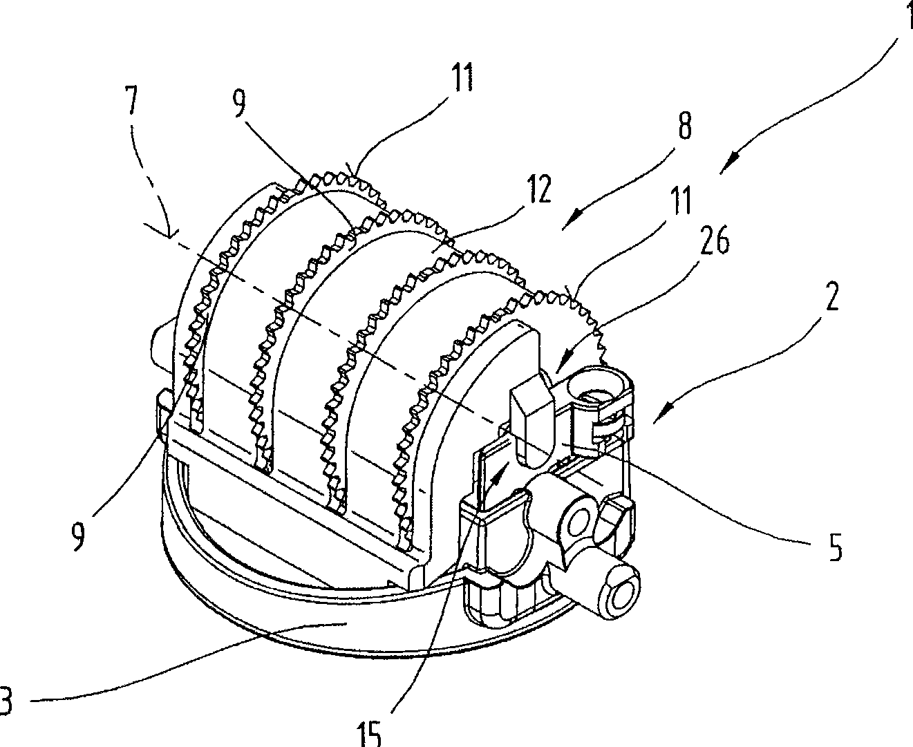
[0035] Figures 1 to 3 illustrate a possible embodiment of a stamp, which can be interpreted as an independent solution in its own right, in particular an insert element 1 with an insert body 2 for a stamp,...


PUM


Abstract

The invention describes a stamp insert (1) with multiple adjustable wheels (9) in a side-by-side formation and seated upon the axis (7) of an insert (2) in such a way that they can rotate. The adjustable wheels (9) are built to carry bands of printing type (10). The bands of printing type (10), at least in the area of the adjustable wheels (9), are enclosed by a cap piece (12) that has ends (19, 20) spatially separated in the direction of the axis (7) and slits (13) to allow the penetration of the circumference (11) of the knurled adjustable wheels. The insert is equipped with at least one coupling device (15) to join the cap element (12) with the adjustable insert (2), said device comprising coupling components (16, 17) that co-operate with one another on the insert (2) and on the cap element (12). The coupling elements (16, 17) are constructed so that the relative direction of the coupling motion of the coupling elements (16, 17) is aligned in the direction of the axis (7) of the insert (2).

Description

technical field [0001] The invention relates to an insert for a stamp, in which several setting wheels arranged next to each other are rotatably mounted on the shaft of the insert, the setting wheels being designed to support a font band, the covering element covering the font at least in the area of ​​the setting wheels The band, in the region of the setting wheel, is in turn provided with a groove through which the setting wheel circumference extends and has at least one coupling means for coupling the cover element with the insert body. Background technique [0002] Document AT000379U1 discloses a cover in the form of a U-shaped metal or plastic body containing a groove through which the setting wheel extends and which covers a font band mounted on the hub of the setting wheel. To hold and secure the cover, the insert has front and rear transverse members extending between the side members, which in turn have grooves for receiving the cover fitted over the typeface band. ...

Claims


Application Information

Patent Timeline
IPC IPC(8): B41K1/10
CPCB41K1/10
Inventor 曼弗雷德·奥特纳
Owner TRODAT GMBH
Learn More