
Double-interlock double-cone energizing pulling shank tensioning mechanism

A double-cone, double-interlocking technology, applied in the direction of the chuck, can solve the problem of loose tool handle fixation, and achieve the effect of increased safety performance and firm fixation

Inactive Publication Date: 2009-08-19
大连机床(数控)股份有限公司
View PDF0 Cites 4 Cited by
  • Summary
  • Abstract
  • Description
  • Claims
  • Application Information

AI Technical Summary

Problems solved by technology

The pulling force of the tensioning mechanism of this structure is small, and the tool handle is not firmly fixed.

Method used


Image

  • Double-interlock double-cone energizing pulling shank tensioning mechanism
  • Double-interlock double-cone energizing pulling shank tensioning mechanism
  • Double-interlock double-cone energizing pulling shank tensioning mechanism

Examples


Embodiment Construction

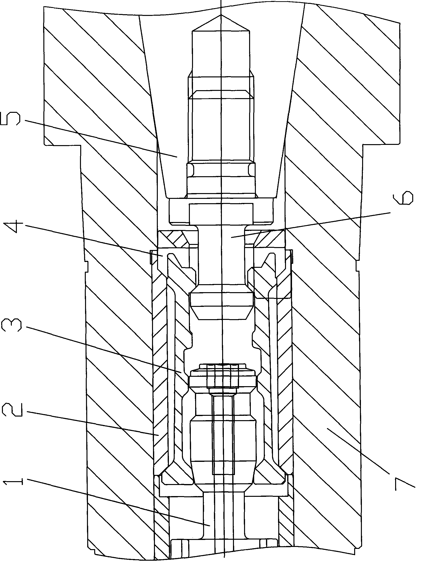
[0016] Such as figure 1 Shown: 7 main shafts, 5 is that the taper surface fits between tool handle and main shaft 7. The handle of a knife 5 is screwed and fastened to the right end of the pull stud 6 . The pull stud 6 is processed with a pull stud tapered surface 11 .

[0017] Such as figure 1 , shown in 5,6: be fixed with unlocking frame 2 at the endoporus place of main same 7, the left end inboard of unlocking frame 2 is processed with unlocking frame cone 13, and the right-hand end is processed with four openings 12 that are evenly distributed on the circumference.

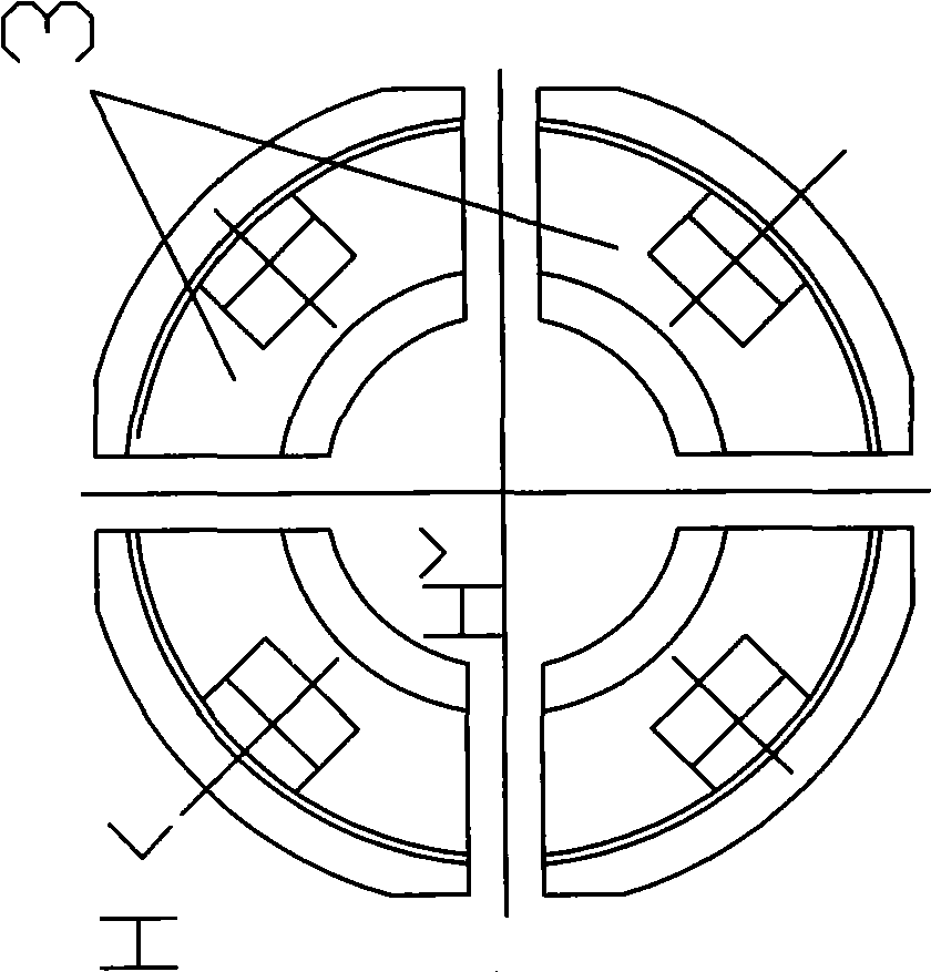
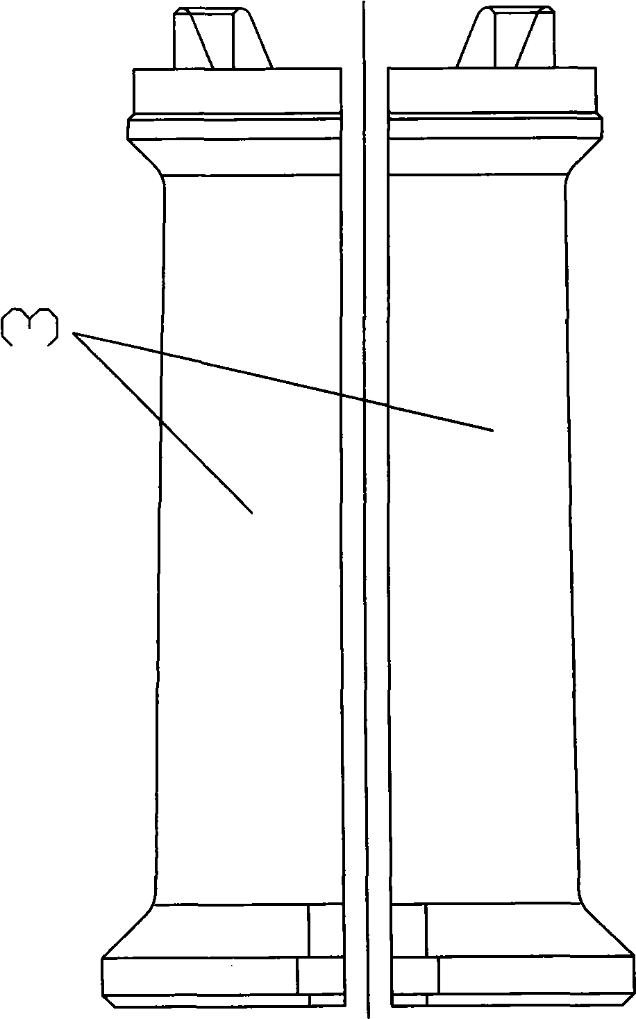
[0018] Such as figure 1 , 2 , Shown in 3, 4, and 6: the inboard of unlocking frame 2 is provided with clamping valve 3, and clamping valve 3 is four, is evenly distributed on the circumference. During processing, the cylindrical whole is processed first, and then cut into four equal parts. Its left end inboard is processed with inner cone 9, and the outside is processed with outer cone 8, and outer cone ...


PUM


Abstract

The invention relates to a pulling cutter handle pulling mechanism for double interlocking and double conical surface reinforcement, which comprises a spindle, a pulling pin and a pulling nail which is connected with the cutter handle. The pulling cutter handle pulling mechanism is characterized in that the inside of the spindle is fixed with an unlocking frame, and at least three clamping petals which are uniformly distributed circumferentially are arranged between the unlocking frame and the pulling pin; the outside at the left end of the clamping petals is provided with an outer conical surface which is matched with an unlocking frame conical surface at the left end inside the unlocking frame, and the inside at the left end of the clamping petals is provided with an inner conical surface which is matched with a pulling pin conical surface on the pulling pin; the middle of the clamping petals is provided with steps; the inside at the right end of the clamping petals is provided with a front conical surface which is matched with a pulling nail conical surface on the pulling nail; and the right end of the unlocking frame is provided with an opening which is matched with an insertion plate on a clamping petal positioning bush, and the clamping petal positioning bush is positioned at the right end of the unlocking frame. The pulling cutter handle pulling mechanism ensures that acting force for pulling the pulling nail is increased, thereby achieving the aim of the double interlocking and double conical surface reinforcement. The cutter handle is tightly fixed, so that the safe performance is improved.

Description

technical field [0001] The invention relates to a tensioning mechanism, in particular to a tensioning mechanism for a double-interlocking double-tapered force-increasing tension tool handle used on a machine tool. Background technique [0002] The tool handle for cutting the workpiece in the machine tool is fixed in the main shaft through a tensioning mechanism. The existing tensioning mechanism has a tapered surface matching the tool handle at one end of the main shaft, and a pull stud connected with the tool handle. The other end is connected to the tensioning mechanism. The pulling pin in the tensioning mechanism is connected with the pulling nail through the clamping valve. spring. When working, the pull pin pulls the pull nail through the clamping valve to fix the tool handle in the main shaft. When the knife is unloaded, the pull pin moves toward the pull rivet. Under the action of the spring, the flap at one end of the pull pin shrinks, and the clip flap at one end ...

Claims


Application Information

Patent Timeline
IPC IPC(8): B23B31/26
Inventor 李小青赵学清胡文祥周建程龙
Owner 大连机床(数控)股份有限公司
Learn More