
Die trimming method

A trimming and mold technology, applied in the direction of metal processing, etc., can solve the problems of complex operation, increased mold processing procedures, high cost, etc., and achieve the effect of reducing costs, reducing procedures, cutting and repairing labor

Inactive Publication Date: 2009-08-19
湖北十堰先锋模具股份有限公司
View PDF0 Cites 2 Cited by
  • Summary
  • Abstract
  • Description
  • Claims
  • Application Information

AI Technical Summary

Problems solved by technology

[0002] At present, for the trimming of stamping parts, the stamping process plan combining tool translational trimming and side trimming is adopted. This trimming method not only increases the process of mold processing, but also is difficult to implement, complicated to operate, and high in cost.

Method used

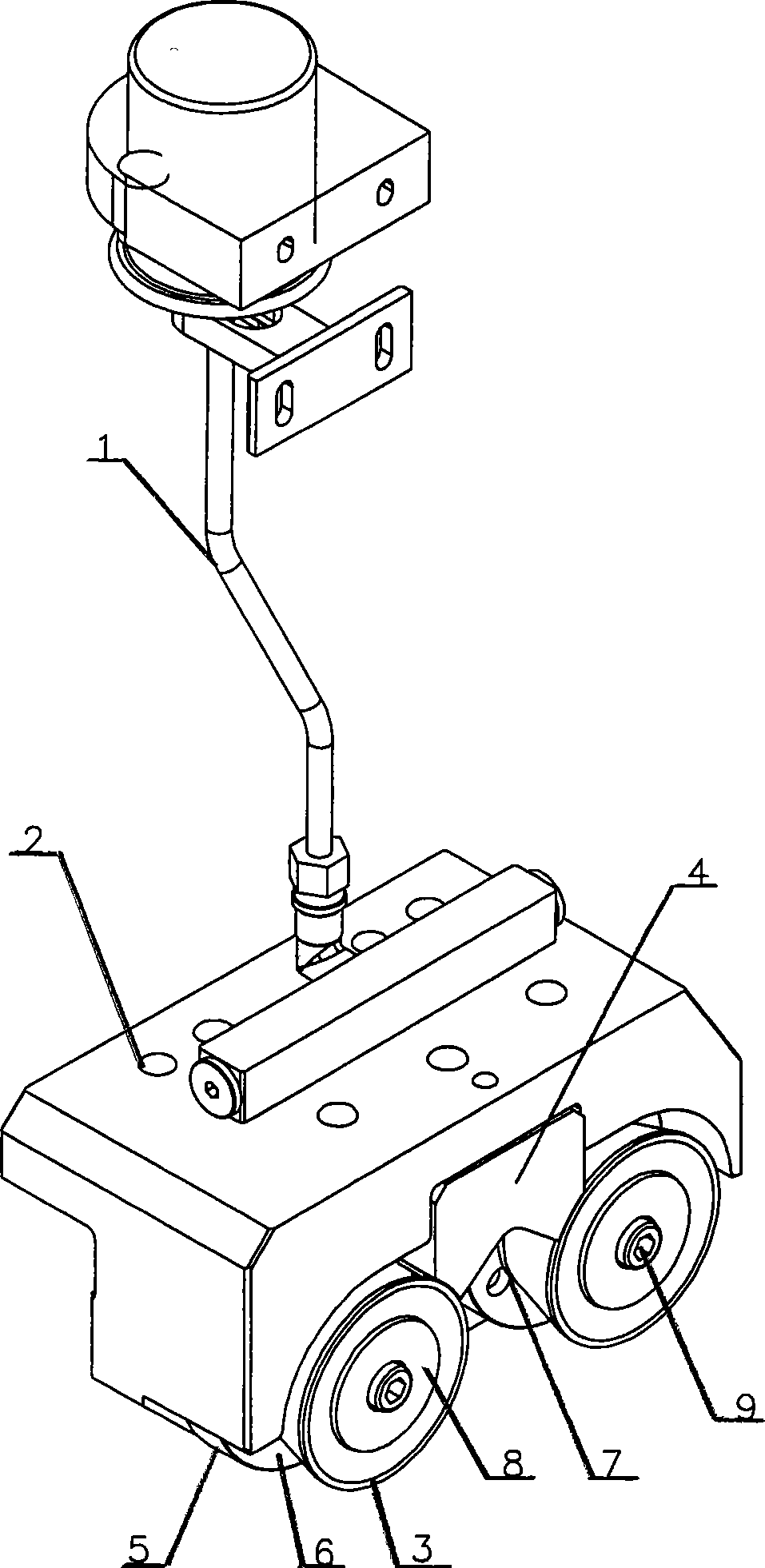

Image

  • Die trimming method

Examples


Embodiment 1

[0015] First, fix the edge trimming mechanism on the upper mold of the mold, so that the cutting edge of the edge trimming mechanism faces the cutting edge of the workpiece, and the edge trimming mechanism moves downward with the upper mold, when the cutting edge of the edge trimming mechanism touches When trimming, the trimming mechanism continues to move downward with the drive of the upper die, and the fixed cutting edge cuts off the trimming edge of the workpiece. This method can complete the trimming of the horizontal edge.

Embodiment 2

[0017] First, fix the edge trimming mechanism on the upper mold of the mold, so that the cutting edge of the edge trimming mechanism faces the cutting edge of the workpiece, and the edge trimming mechanism moves downward with the upper mold, when the cutting edge of the edge trimming mechanism touches When trimming, the trimming mechanism continues to move downward with the drive of the upper die, and the rotating cutting blade on the side of the fixed cutting blade starts to rotate around the central axis to cooperate with the fixed cutting blade until the cutting edge of the workpiece is cut off. Straight side trimming can be done.

Embodiment 3

[0019] First, fix the edge trimming mechanism on the upper mold of the mold, so that the cutting edge of the edge trimming mechanism faces the cutting edge of the workpiece, and the edge trimming mechanism moves downward with the upper mold, when the cutting edge of the edge trimming mechanism touches When trimming, the trimming mechanism continues to move downward with the drive of the upper die, and the rotating cutting blades on both sides of the fixed cutting blade start to rotate around the central axis to cooperate with the fixed cutting blade until the trimming edge of the workpiece is cut off to complete the U-shape Edge trimming.


PUM


Abstract

The invention provides a method for trimming a mould, which comprises the following steps that: a trimming mechanism is first fixed on an upper mould of the mould to ensure that the cutting blade of the trimming mechanism faces an edge to be cut of a workpiece; the trimming mechanism moves with the upper mould in the same direction; and when the cutting blade of the trimming mechanism contacts the edge to be cut of the workpiece, the trimming mechanism is driven by the upper mould to move continuously and the cutting blade starts to work until the cutting is finished. By adopting the method for trimming the mould, the cutting blade is always positioned in the normal direction of the workpiece in the trimming process; the conventional translational trimming is converted into rolling trimming so that the cutting is more labor-saving and order and the working procedures are effectively reduced and the cost is reduced.

Description

technical field [0001] The invention belongs to the technical field of molds, and in particular relates to a method for edge trimming of molds. Background technique [0002] At present, for the trimming of stamping parts, the stamping process plan combining tool translational trimming and side trimming is adopted. This trimming method not only increases the process of mold processing, but also is difficult to implement, complicated to operate, and high in cost. Contents of the invention [0003] The invention provides a method for trimming the mold, which can simplify the machining process of the mold, and has simple operation and low cost. [0004] In order to solve the above-mentioned technical problems, the technical solution of the present invention is as follows: the method for trimming the mold, the steps are as follows: first, the trimming mechanism is fixed on the upper mold of the mould, and the cutting edge of the trimming mechanism is turned towards the cutting ...

Claims


Application Information

Patent Timeline
Patent Type & Authority Applications(China)
IPC IPC(8): B26D1/01B26D1/14
Inventor 朱靖杨红波郭大治夏天宝王涛何毅付勇智
Owner 湖北十堰先锋模具股份有限公司
Learn More