Trimming and punching die for rear connecting cross beam of panoramic sunroof
What is Al technical title?
Al technical title is built by PatSnap Al team. It summarizes the technical point description of the patent document.
A technology of trimming punching die and connecting beams, which is applied in the direction of perforating tools, forming tools, peeling devices, etc., can solve the problems of needing to stop for cleaning, large labor cost investment, low processing efficiency, etc., to reduce costs and improve use. Longevity and effect of improving accuracy
Inactive Publication Date: 2019-04-12
天津希利汽车部品有限公司
View PDF13 Cites 1 Cited by
Summary
Abstract
Description
Claims
Application Information
AI Technical Summary
This helps you quickly interpret patents by identifying the three key elements:
Problems solved by technology
Method used
Benefits of technology
Problems solved by technology
[0004] In view of the above problems, the object of the present invention is to propose a punching die for trimming the connecting beam behind the panoramic sunroof. The present invention can automatically clean up the waste produced after punching through the waste chute and the waste chute plate, which solves the problem of existing problems. In the technology, too much waste after punching needs to be shut down to clean up, resulting in low processing efficiency and large labor costs. In the present invention, there are two lower die inserts and four upper die inserts, two lower die inserts, and two lower die inserts. The mold insert is detachably connected to the lower mold body, and the four upper mold inserts are detachably connected to the upper mold body. The invention can replace worn inserts in a targeted manner without replacing the entire insert, and has the advantages of reducing costs. , and the advantages of improving the service life of the mold
Method used
Image
Click on the blue label to locate the original text in one second.
Reading with bidirectional positioning of images and text.
Examples
Embodiment 1
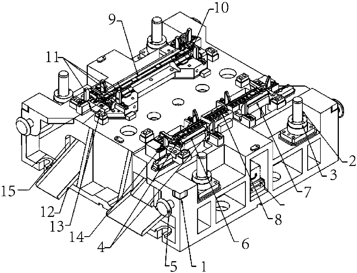
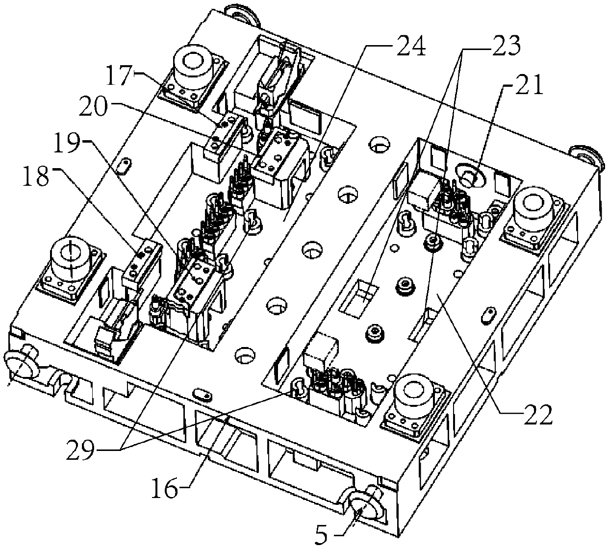
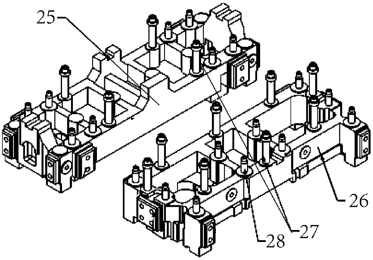
[0035] figure 1 It is a schematic diagram of the three-dimensional structure of the lower mold body in the present invention, figure 2 It is a schematic diagram of the three-dimensional structure of the upper mold body in the present invention, image 3 It is a schematic diagram of the three-dimensional structure of the two pressing core boards in the present invention. Such as figure 1 , figure 2 and image 3The rear connecting beam trimming punching die for a panoramic sunroof shown includes: a lower die body 1, a guide column 2, a travel limit block 3, a positioning key 4, a lifting rod 5, a first lower die insert 6, The second lower mold insert 7, slide frame 8, slide plate 9, slide plate support seat 10, balance pad 11, waste chute plate 12, polyurethane shock absorber 13, side limit block 14, waste slide Groove 15, upper mold body 16, first upper mold insert 17, second upper mold insert 18, third upper mold insert 19, fourth upper mold insert 20, side positioning ...
PUM
Abstract
The invention aims to provide a trimming and punching die for a rear connecting cross beam of a panoramic sunroof. The trimming and punching die comprises a lower die body, guiding columns, travel limiting blocks, positioning keys, lifting bars, a first lower die insert, a second lower die insert, a sliding frame, a sliding plate, a sliding plate supporting seat, balance cushion blocks, a waste sliding chute plate, polyurethane shock-absorbing blocks, side limiting blocks, a waste sliding chute, an upper die body, a first upper die insert, a second upper die insert, a third upper die insert, afourth upper die insert, side positioning pins, a first groove, connecting clamping grooves, a second groove, a first pressing core plate, a second pressing core plate, spring positioning pins and clamping columns. According to the trimming and punching die, the two lower die inserts and the four upper die inserts are arranged, the two lower die inserts are detachably connected with the lower diebody, and the four upper die inserts are arranged are detachably connected with the upper die body, so that the worn inserts can be replaced in a targeted manner, the whole inserts are not required to be replaced, and the trimming and punching die has the advantages that the cost is reduced and the service life of the die is prolonged.
Description
technical field [0001] The invention relates to the technical field of welding equipment, in particular to a trimming and punching die for a rear connecting beam of a panoramic sunroof. Background technique [0002] At present, the panoramic sunroof in the car has become a bright spot in the middle and high-end cars. However, due to the larger size of the panoramic sunroof, higher requirements are put forward for the structure of the car body, the precision of stamping parts, and the manufacturing process of the car body. The air is fresh, and the peculiar smell inside the car can be quickly removed; the super enjoyment of looking up at the sky; and when driving at high speed, it can reduce the noise inside the car more effectively than the side window; it can also quickly reduce the temperature inside the car It's a pretty good cooler for a car. At present, when processing the connecting beam behind the panoramic sunroof of an automobile, it is often necessary to perform ...
Claims
Application Information
Patent Timeline
Application Date:The date an application was filed.
Publication Date:The date a patent or application was officially published.
First Publication Date:The earliest publication date of a patent with the same application number.
Issue Date:Publication date of the patent grant document.
PCT Entry Date:The Entry date of PCT National Phase.
Estimated Expiry Date:The statutory expiry date of a patent right according to the Patent Law, and it is the longest term of protection that the patent right can achieve without the termination of the patent right due to other reasons(Term extension factor has been taken into account ).
Invalid Date:Actual expiry date is based on effective date or publication date of legal transaction data of invalid patent.