
Transport and storage container for liquids
A container and liquid technology, applied in the field of liquid transportation and storage containers, can solve problems such as the net weight of storage containers, and achieve the effects of reducing manufacturing costs, reducing net weight, and reducing material strength
- Summary
- Abstract
- Description
- Claims
- Application Information
AI Technical Summary
Problems solved by technology
Method used
Image

Examples
Embodiment Construction
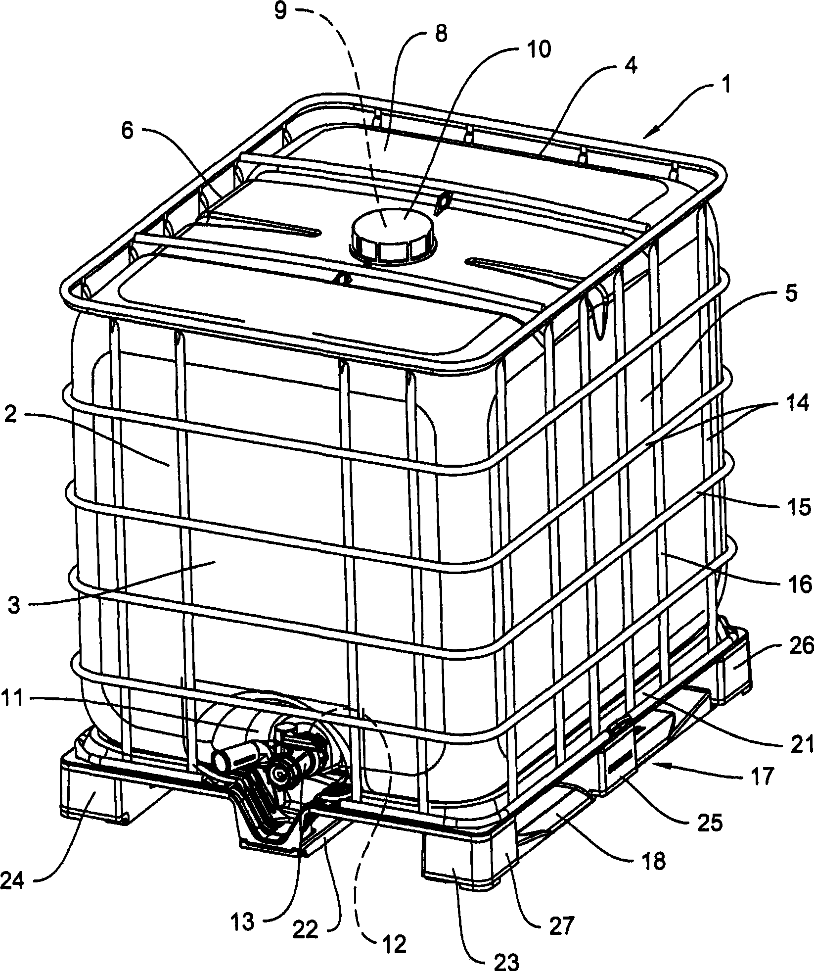
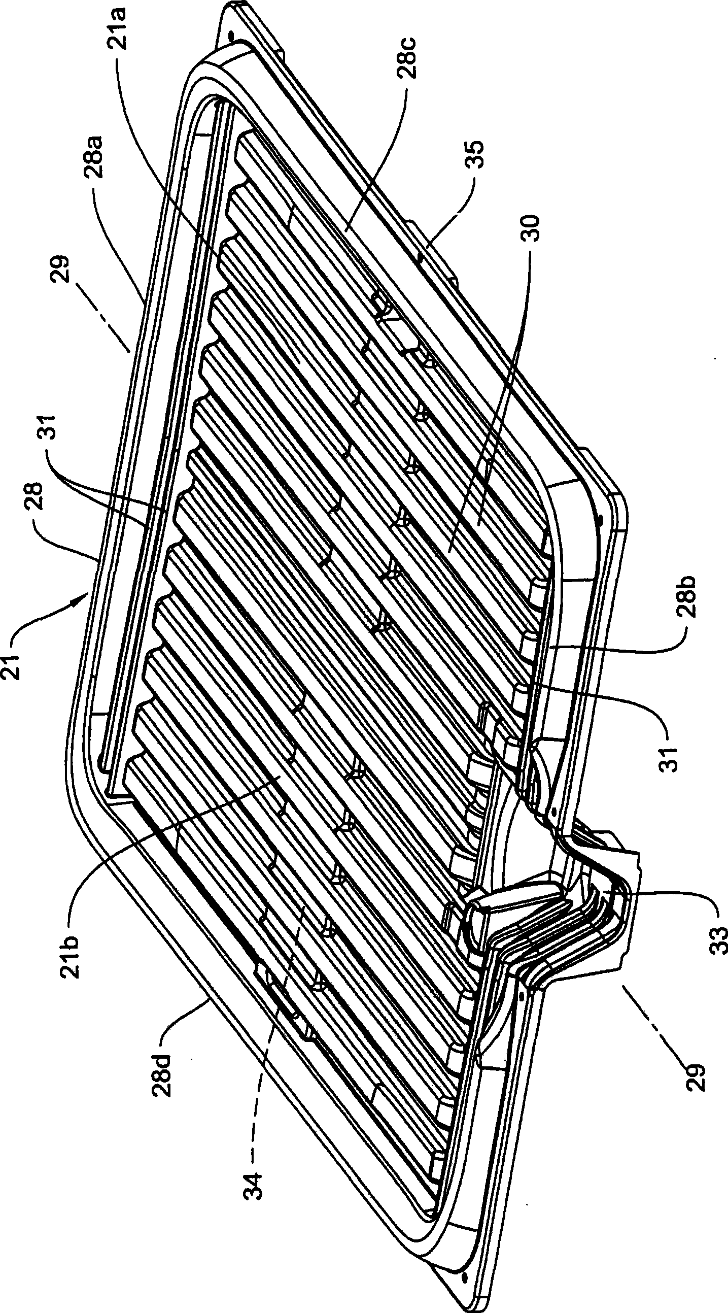
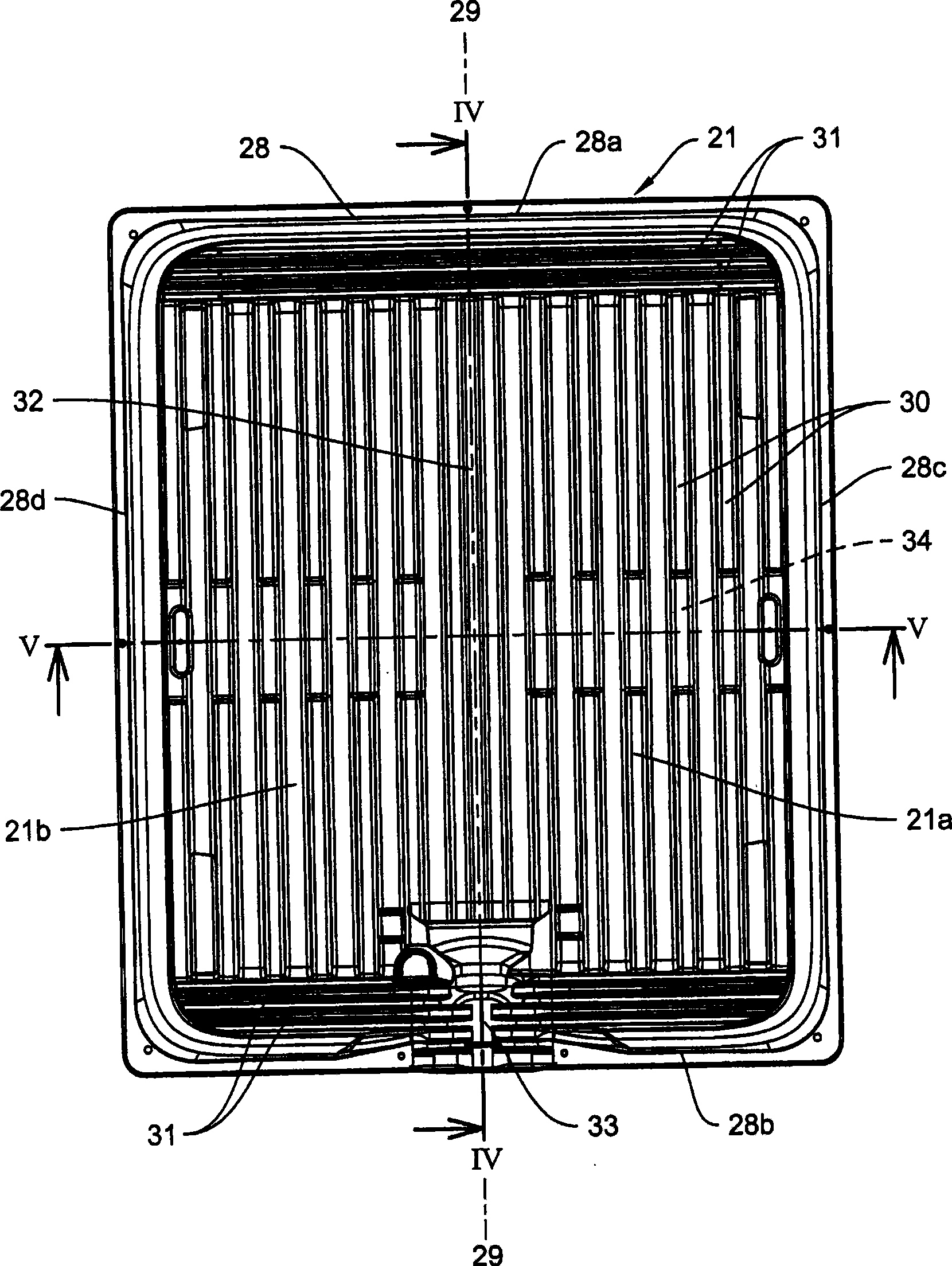
[0016] according to figure 1 , a transport and storage container for liquids 1 that can be used as a single-use or reusable container has the following main parts: replaceable cuboid-shaped inner container 2 made of plastic, crossed horizontal and vertical The grid bars 15, 16 are constructed as an outer shell 14 of the grid housing and a pallet-type base 17 with length and width dimensions according to European standards; the inner container 2 has a front wall 3, a rear wall 4 and two side walls 5, 6, the lower bottom 7 and the upper bottom 8, the injection sleeve 9 formed on the upper bottom 8 which can be closed with a cover 10 and the connection sleeve 12 formed at the recess 11 in the lower part of the front wall 3, the connection sleeve 12 is used to connect the take-out device 13; the shell 14 is used to receive the inner container 2, and the inner container 2 is placed on the base 17. The lower bottom 7 of the inner container 2, configured as a discharge bottom, is di...
PUM
 Abstract
Description
Claims
Application Information