Ventilation valve for a vehicle

A technology for ventilation valves and vehicles, which is applied in the field of ventilation valves for wind, and can solve problems such as leakage of ventilation valves

Inactive Publication Date: 2019-07-19
ILLINOIS TOOL WORKS INC
View PDF3 Cites 0 Cited by
  • Summary
  • Abstract
  • Description
  • Claims
  • Application Information

AI Technical Summary

Problems solved by technology

However, such flaps have the disadvantage that the restoring force of the flap decreases considerably over time due to material fatigue phenomena, which leads to leakage of the ventilation valve

Method used


Image

  • Ventilation valve for a vehicle
  • Ventilation valve for a vehicle
  • Ventilation valve for a vehicle

Examples


Embodiment Construction

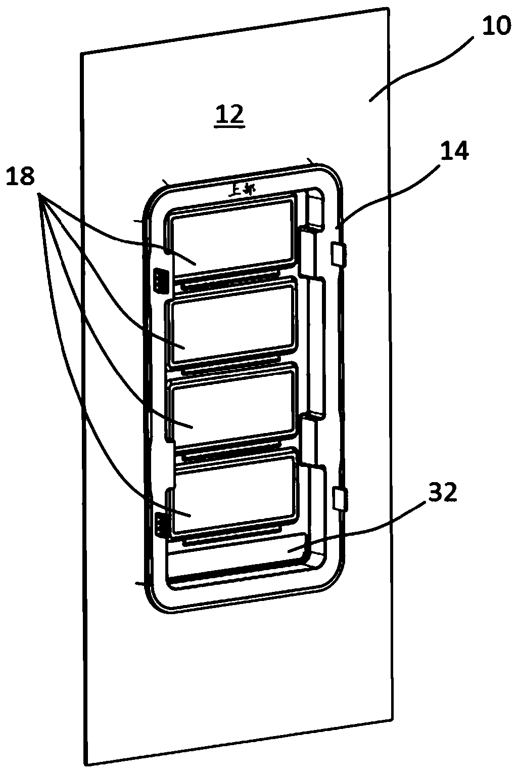
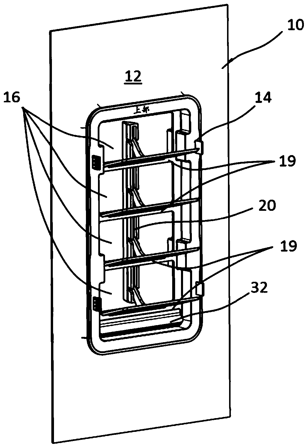
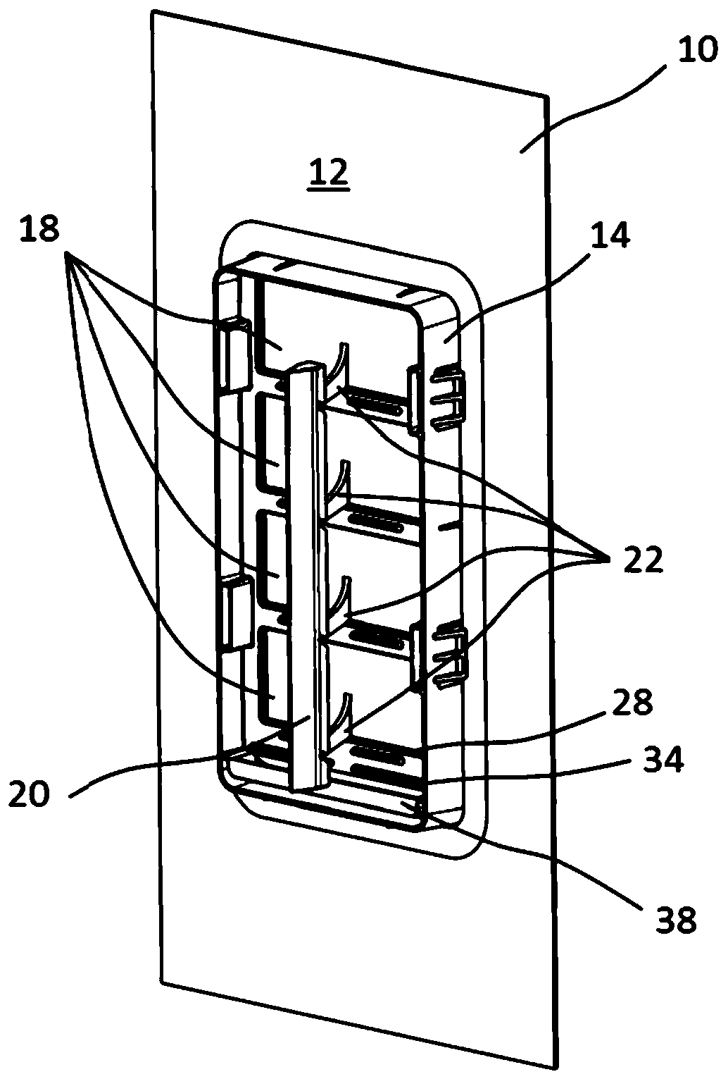
[0037] exist Figure 1-8 An exemplary embodiment of a ventilation valve according to the invention is shown in .

[0038] The ventilation valve 10 comprises a mounting plate 12 into which a valve frame 14 is embedded. The valve housing 14 is here fixed to the mounting plate 12 via snap-in projections 15 and contact edges 17 . The contact edge 17 simultaneously forms a seal against the mounting plate 12 . Four through-openings 16 are formed in the valve housing 14 and are separated from one another by webs 19 . The ventilation flap 18 is mounted on the web 19 , wherein the pivot bearing 28 of the ventilation flap 18 engages for this purpose in the pivot bearing receptacle 30 of the web 19 . The ventilation flap 18 can thus be in figure 1 , 3 , 5 and 8 in the closed position (in which the ventilation flap covers the through opening 16) and in figure 2 , 4 , 6 and 9 shown in the open position (in the open position the ventilation flaps open the through opening 16) between...


PUM


Abstract

The invention relates to a ventilation valve for ventilating the interior of a vehicle, comprising a valve frame with at least one through opening, and also at least one ventilation flap which is mounted on the valve frame and is pivotable between a closed position and an open position, wherein the at least one ventilation flap closes the at least one through opening in the closed position and opens up the at least one through opening in the open position, which comprises resetting means for pivoting the at least one ventilation flap back out of the open position into the closed position.

Description

[0001] field of invention [0002] The invention relates to a ventilation valve (Entlüftungsventil) for ventilating an interior space of a vehicle, comprising a valve frame with at least one through-opening and at least one valve mounted on the valve frame, which can be moved between a closed position and an open position. The at least one ventilation flap closes the at least one through opening in the closed position and opens the at least one through opening in the open position. Background technique [0003] Such a ventilation valve serves to remove escaping air from the vehicle interior in the event of a positive pressure in the vehicle interior relative to the vehicle surroundings. Air supplied to the vehicle interior, for example via a ventilation system, can thus be removed. In particular, a sudden positive pressure in the vehicle interior (generated, for example, by closing a vehicle door or by triggering an airbag) can be compensated by allowing excess air to flow fr...

Claims


Application Information

Patent Timeline
IPC IPC(8): F16K24/04F16K1/20B60H1/26
CPCF16K24/04F16K1/2021B60H1/26B60H1/249B60H2001/006F24F13/15
Inventor 安德鲁·莱费弗史蒂芬·姚茨克休伯特·勒韦
Owner ILLINOIS TOOL WORKS INC
Why Eureka
Try Eureka