Backlight module and optoelectronic device

A technology for a backlight module and a light-emitting device, which is applied to lighting devices, fixed lighting devices, components of lighting devices, etc., can solve problems such as difficult rework procedures, simplify assembly and rework procedures, reduce light source damage, and improve assembly positioning. The effect of precision

Active Publication Date: 2009-08-19
AU OPTRONICS CORP
View PDF0 Cites 8 Cited by
  • Summary
  • Abstract
  • Description
  • Claims
  • Application Information

AI Technical Summary

Problems solved by technology

In addition, when the backlight module 100 needs to be reworked (rework process), it is necessary to overcome the stickiness and residual problems of the glue, so the rework process is not easy to carry out.

Method used


Image

  • Backlight module and optoelectronic device
  • Backlight module and optoelectronic device
  • Backlight module and optoelectronic device

Examples


Embodiment Construction

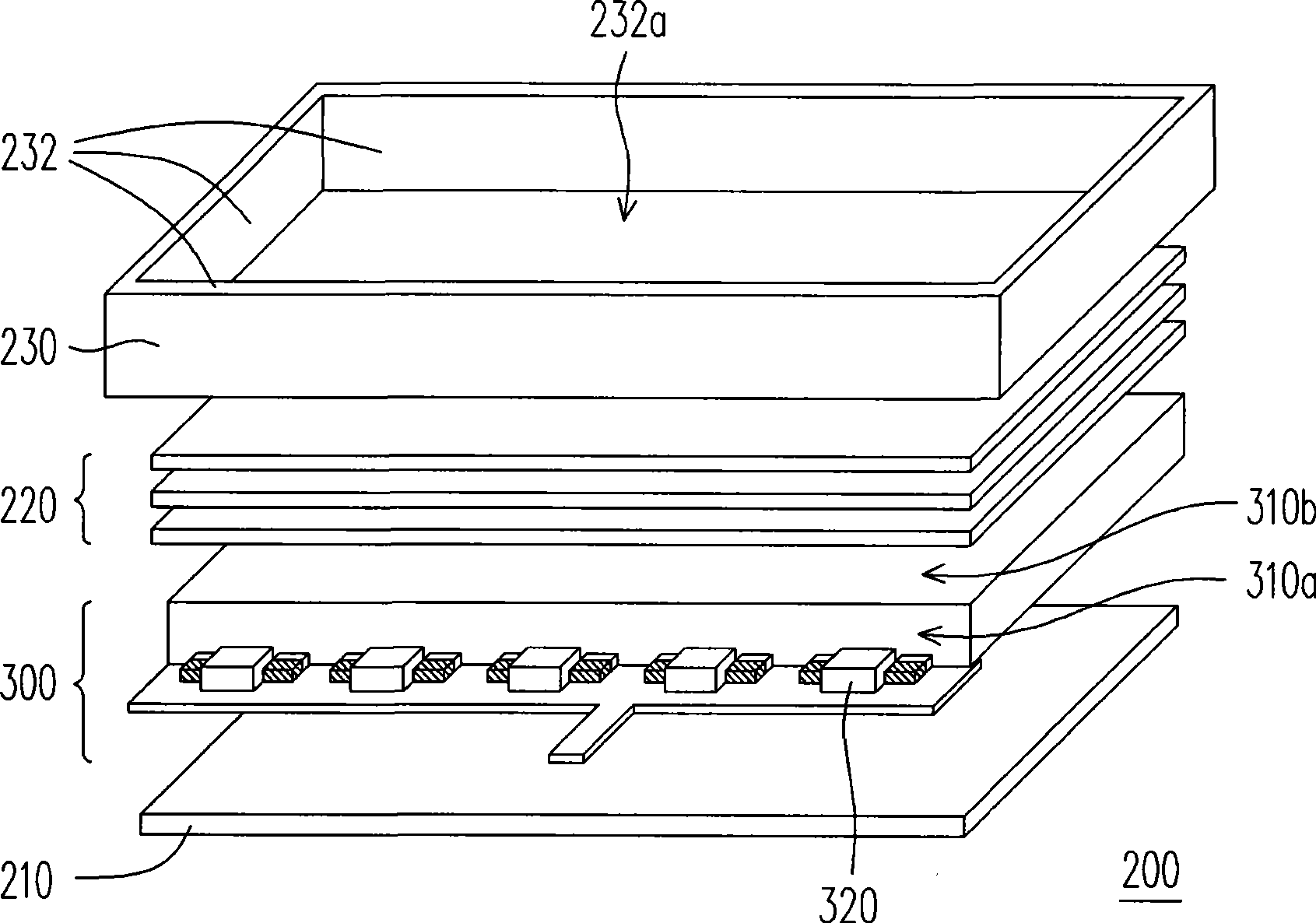
[0053] figure 2 It is an exploded schematic diagram of the backlight module 200 of the preferred embodiment of the present invention. Figure 3A for figure 2 A schematic diagram of the local components of the backlight module. Figure 3B for Figure 3A side view diagram. In this embodiment, the backlight module 200 is a side-facing backlight module, and Figure 3A and Figure 3B for figure 2 The schematic diagram of the light guide plate and the circuit board in the light emitting device 300 before assembly.

[0054] Please refer to figure 2 , Figure 3A and Figure 3B The backlight module 200 includes a light emitting device 300 , preferably, the backlight module 200 further includes a reflector 210 , an optical sheet group 220 and a frame 230 . The reflection plate 210 is disposed under the light emitting device 300 . The optical sheet group 220 is disposed above the light emitting device 300 . The accommodating side 232 of the frame 230 defines an accommodat...


PUM


Abstract

The invention relates to a backlight module and a photoelectric device, the backlight module comprises an optical plate and at least one light emitting element. The optical plate comprises a light-incoming face and a light-exiting face. The light emitting element is arranged on a circuit board and faces toward the light-incoming face, wherein, the light emitting element is magnetically absorbed on the optical plate by making use of at least one magnetic absorption member that is arranged on at least one or both of the optical plate and the circuit board. On account of using the magnetic absorption member for the assembly, the assembly positioning precision of the backlight module can be improved and the risk that the light emitting element is damaged can be reduced.

Description

technical field [0001] The invention relates to a backlight module and a photoelectric device, and in particular to a backlight module capable of precise positioning and assembly and a photoelectric device with a simple assembly procedure. Background technique [0002] In general liquid crystal displays, since the liquid crystal display panel (Liquid crystal display panel) does not have the function of actively emitting light, the liquid crystal display panel must be equipped with a backlight to display images. [0003] Figure 1A and Figure 1B It is a schematic diagram of a conventional side-type backlight module 100 . Please refer to Figure 1A , in the prior art, the circuit board 110 provided with the light emitting element 120 is fixed on the plastic frame 130 or the light guide plate 140 by using glue (not shown). However, the above method of fixing with glue is likely to cause a gap d between the light guide plate 140 and the light emitting element 120 due to the d...

Claims


Application Information

Patent Timeline
IPC IPC(8): F21S8/00F21V8/00F21V19/00G02F1/13357F21Y101/02G02F1/1335
Inventor 张启鸿杨青桑邓友渊
Owner AU OPTRONICS CORP
Why Eureka
Try Eureka