A Part Surface Design Method for Improving Visual Recognition of Automatic Assembly

A visual recognition and automatic assembly technology, which is applied in the field of part surface design, can solve the problems that the quality of the picked up image does not fully meet the definition requirements and the difficulty of machining, so as to improve the ability of automatic deviation correction, reduce the difficulty of processing, and reduce the cost of development Effect

Active Publication Date: 2020-09-18
BEIJING RES INST OF TELEMETRY +1
View PDF6 Cites 0 Cited by
  • Summary
  • Abstract
  • Description
  • Claims
  • Application Information

AI Technical Summary

Problems solved by technology

Usually, Mark features are set during the visual design of assembly parts, including points, lines, holes and other features. The picked-up image quality does not fully meet the definition requirements

Method used


Image

  • A Part Surface Design Method for Improving Visual Recognition of Automatic Assembly
  • A Part Surface Design Method for Improving Visual Recognition of Automatic Assembly
  • A Part Surface Design Method for Improving Visual Recognition of Automatic Assembly

Examples


Embodiment

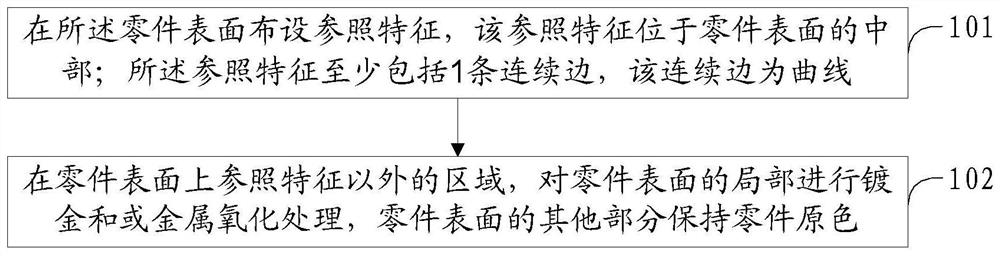
[0035] A part surface design method for improving automatic assembly visual recognition, comprising the following steps:

[0036] (1) When designing a part, a reference feature is arranged in the center of the part plane. The position accuracy of the reference feature in the part plane is the highest. The reference feature can be a positioning hole, a positioning pin or a reference edge. The reference feature is used as the benchmark reference feature during part design, and it is ensured that the reference feature has little wear and tear due to clamping or daily transportation, which will affect the line quality of the image during automatic assembly visual recognition; in addition, the reference feature should be as close as possible The center of the part surface, while ensuring that the reference feature will not be blocked after the part surface is assembled.

[0037] (2) Add a sharp color contrast to the surface treatment of the visual recognition area of ​​the part. Go...

no. 1 example

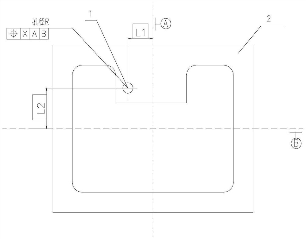
[0040] Such as figure 2 As shown, the assembly part 2 is provided with a high-precision positioning pin hole 1. Since the centerline of the whole part is used as the processing and marking reference of the part, it cannot directly reflect the visual area of ​​the reference, and the positioning pin hole 1 is marked with dimensions L1, L2 and The position tolerance X is based on the center line, and it is the hole with the highest precision based on the marked datum, and this hole is not easy to be damaged by bumps, so it is selected as a reference feature and a visual identification item.

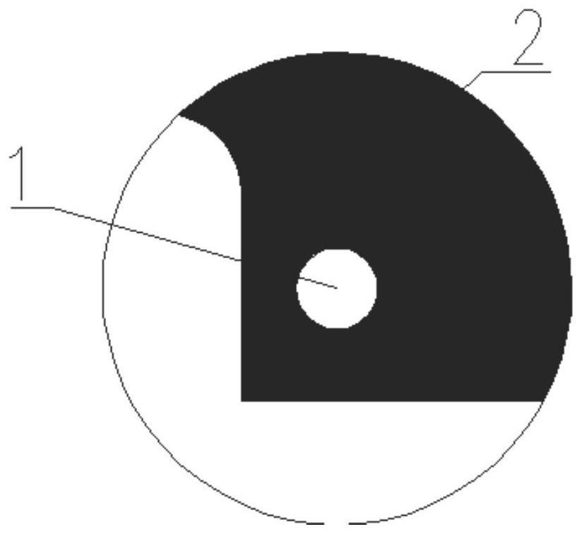
[0041] When the surface treatment of the assembly part 2 is carried out, since the whole part is made of aluminum, the surface needs to be treated with black anodization to meet the emissivity requirements, while the inner surface of the pin hole 1 can be protected, and only the natural color conductive oxidation is done, such as image 3 As shown, the natural color is the conductive oxidat...

no. 2 example

[0043] Such as Figure 4 As shown, the reference reference line 3 for part processing is arranged on the assembly part 2. Since the assembly part 2 considers other installation fits, the edges within the range of the reference reference line 3 are used as the processing X and Y references, that is, the dimensions H1, H2, Both W1 and W2 are marked with X and Y axes. Since these two sides have the highest machining accuracy, they can be regarded as visual identification items.

[0044]The assembly part 2 is a metal aluminum part, which needs to be gold-plated in order to meet the weldability. The method of the present invention is applied to the part plating treatment to adopt a local treatment method. The welding area needs gold-plating treatment, and other areas need to be conductively oxidized in natural color, such as Figure 5 As shown, 4 is the conductive oxidation area of ​​the natural color, which does not require welding, and 5 is the gold-plated area, which needs to me...


PUM


Abstract

The invention relates to a part surface design method capable of improving automatic assembling visual identity. The part surface design method comprises the following steps of step I, arranging a reference characteristic on the surface of a part, wherein the reference characteristic is located at the middle part of the surface of the part, the reference characteristic at least comprises one continuous edge, and the continuous edge is a curve; and step II, locally performing gold-plating treatment or metal oxidation treatment on the surface of the part on a region except the reference characteristic on the surface of the part, and enabling the other part of the surface of the part to maintain the primary color of the part. Through the adoption of the method disclosed by the invention, therecognition degree of the visual identity of the part surfaces is high, and the clarity of a visual sense template is higher, so that the automatic deviation correcting capacity of an assembling robotis improved, the surface treatment manner having color differences is easy to realize, and development cost cannot be increased.

Description

technical field [0001] The invention relates to a part surface design method for improving automatic assembly visual recognition, which is suitable for the structural design field of automatic assembly micro-assembled electronic products. Background technique [0002] The automatic assembly production line uses modern production technology to replace traditional manual labor with robots, so that robots and assembly equipment are organically combined, and the batch assembly, testing, labeling and packaging of products are completed under the joint action of the conveying system and assembly equipment. process. During the automatic assembly process, the visual recognition of the robot can guide the robot to perform visual correction, so as to ensure that the robot can accurately install the accessories in place. [0003] The visual recognition of intelligent robots is based on the establishment of visual templates, compares the templates with the information of the picked up ...

Claims


Application Information

Patent Timeline
Patent Type & Authority Patents(China)
IPC IPC(8): B23P19/00
CPCB23P19/00
Inventor 高倩郑洋王丽菊唐统帅蒋德怀刘德喜史磊
Owner BEIJING RES INST OF TELEMETRY
Why Eureka
Try Eureka