Back light module and liquid crystal display device
A technology for backlight modules and liquid crystal display panels, which is applied to lighting devices, static indicators, components of lighting devices, etc., can solve the problems of increasing material costs, reducing the flexibility of space utilization in structural design, and reducing usage. Effect
Inactive Publication Date: 2011-01-05
CPT TECH GRP
View PDF0 Cites 0 Cited by
- Summary
- Abstract
- Description
- Claims
- Application Information
AI Technical Summary
Problems solved by technology
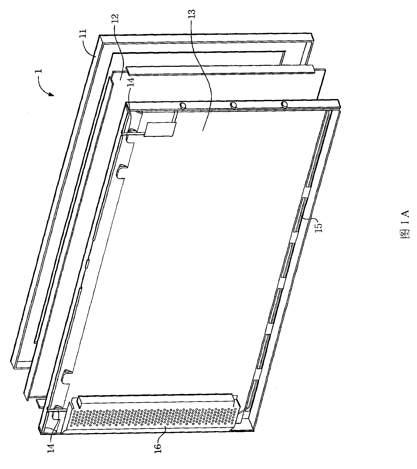
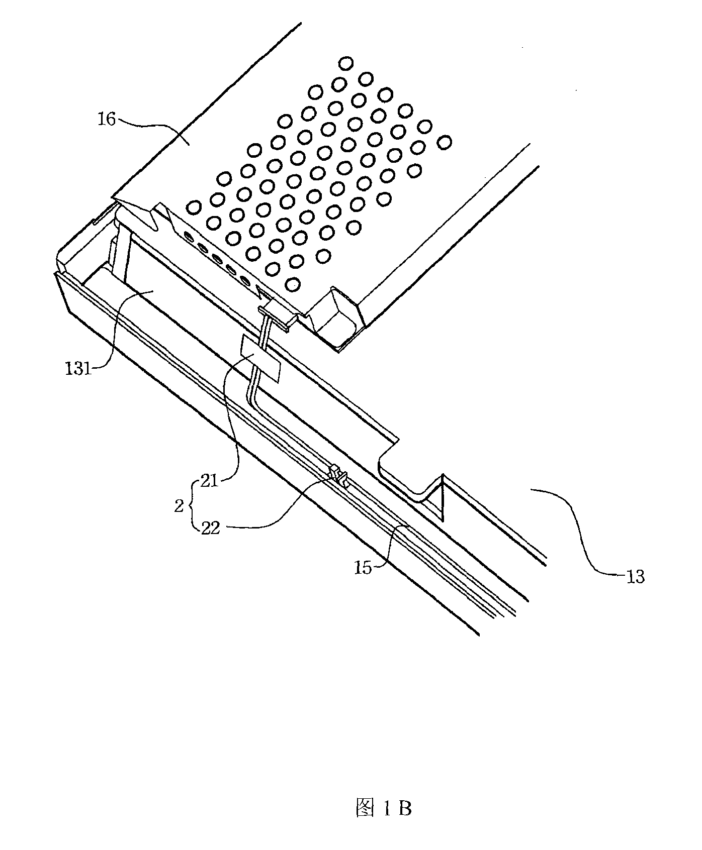
However, no matter using an adhesive tape structure 21 or a fixing base 22 to attach and fix the wire, it is an additional new component, which will not only increase the cost of some materials, but also may reduce the structural design. Flexibility of space utilization
Method used
View moreImage
Smart ImageViewing Examples
Examples
Embodiment Construction
Login to View More PUM
 Abstract
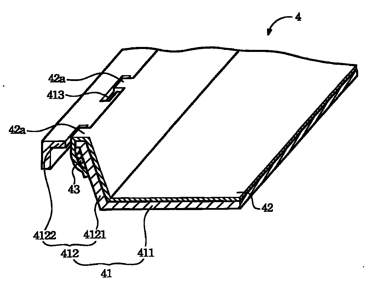
A backlight module is disclosed, which is applied to a liquid crystal display. The backlight module at least comprises a back frame, a first optical film and at least one wire; wherein, the back frame comprises a soleplate and a sidewall extending upwards from the circumference of the soleplate, and the back frame includes at least one opening; the first optical film is arranged on the soleplate and extends upwards along the sidewall; the wire is located in the outer side of the back frame, partial optical film can extend to the outer side of the back frame via the opening on the back frame in order to fix the wire on the outer surface of the back frame. The backlight module provided by the invention and a liquid crystal display device comprising the backlight module directly use the extension part of the original first optical film to fix the wire, thus efficiently decreasing the use amount of adhering materials and fixing materials, and as no new assembly is added, space utilizationof the structural design is not influenced.
Description
Backlight module and liquid crystal display device technical field The invention relates to a backlight module, in particular to a backlight module using an extension part of an optical film to fix wires and a liquid crystal display device comprising the backlight module. Background technique With the advancement of science and technology, liquid crystal displays with many advantages such as power saving, no radiation, small size, low power consumption, flat right-angle, high resolution, stable image quality, etc., are the traditional image tube screens that used to be in the exclusive position ( CRT for short) has brought a great impact, especially nowadays various information products such as mobile phones, notebook computers, digital cameras, PDAs, LCD screens and other products are becoming more and more popular, which also makes the demand for liquid crystal displays (LCD) Huge improvements. The liquid crystal display mainly includes a liquid crystal display panel a...
Claims
Login to View More Application Information
Patent Timeline
 Patent Type & Authority Patents(China)
IPC IPC(8): G02F1/13357F21V17/00G02F1/133
Inventor 谢忠志余祥文
Owner CPT TECH GRP
Features
- R&D
- Intellectual Property
- Life Sciences
- Materials
- Tech Scout
- Unparalleled Data Quality
- Higher Quality Content
- 60% Fewer Hallucinations
Learn More Browse by: Latest US Patents, China's latest patents, Technical Efficacy Thesaurus, Application Domain, Technology Topic, Popular Technical Reports.
© 2025 PatSnap. All rights reserved.Legal|Privacy policy|Modern Slavery Act Transparency Statement|Sitemap|About US| Contact US: help@patsnap.com


