Self-regulating levitation wind power generation system

A wind power generation system and self-adjusting technology, which is applied in the direction of wind power generation, wind power engine, wind power motor combination, etc., can solve problems such as insufficiency, and achieve the effect of high power generation efficiency, large moment of inertia, and small maintenance workload

Inactive Publication Date: 2009-08-19
刘新广
View PDF0 Cites 7 Cited by
  • Summary
  • Abstract
  • Description
  • Claims
  • Application Information

AI Technical Summary

Problems solved by technology

In order to improve the efficiency of power generation, various wind rotors and generators and their combinations have been developed, but they are not enough.

Method used


Image

  • Self-regulating levitation wind power generation system
  • Self-regulating levitation wind power generation system
  • Self-regulating levitation wind power generation system

Examples


Embodiment 1

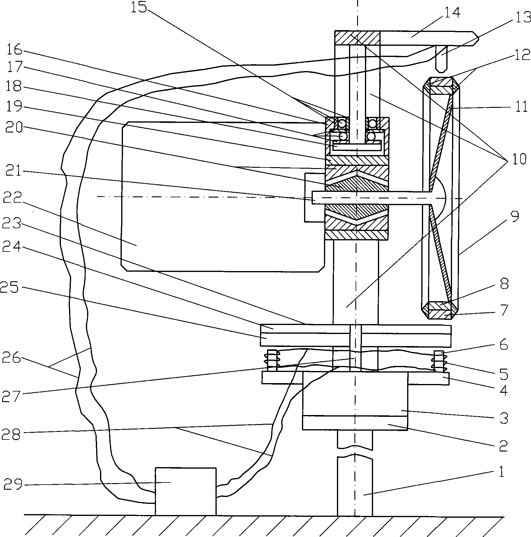
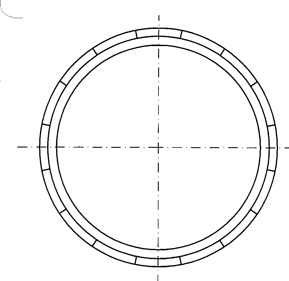
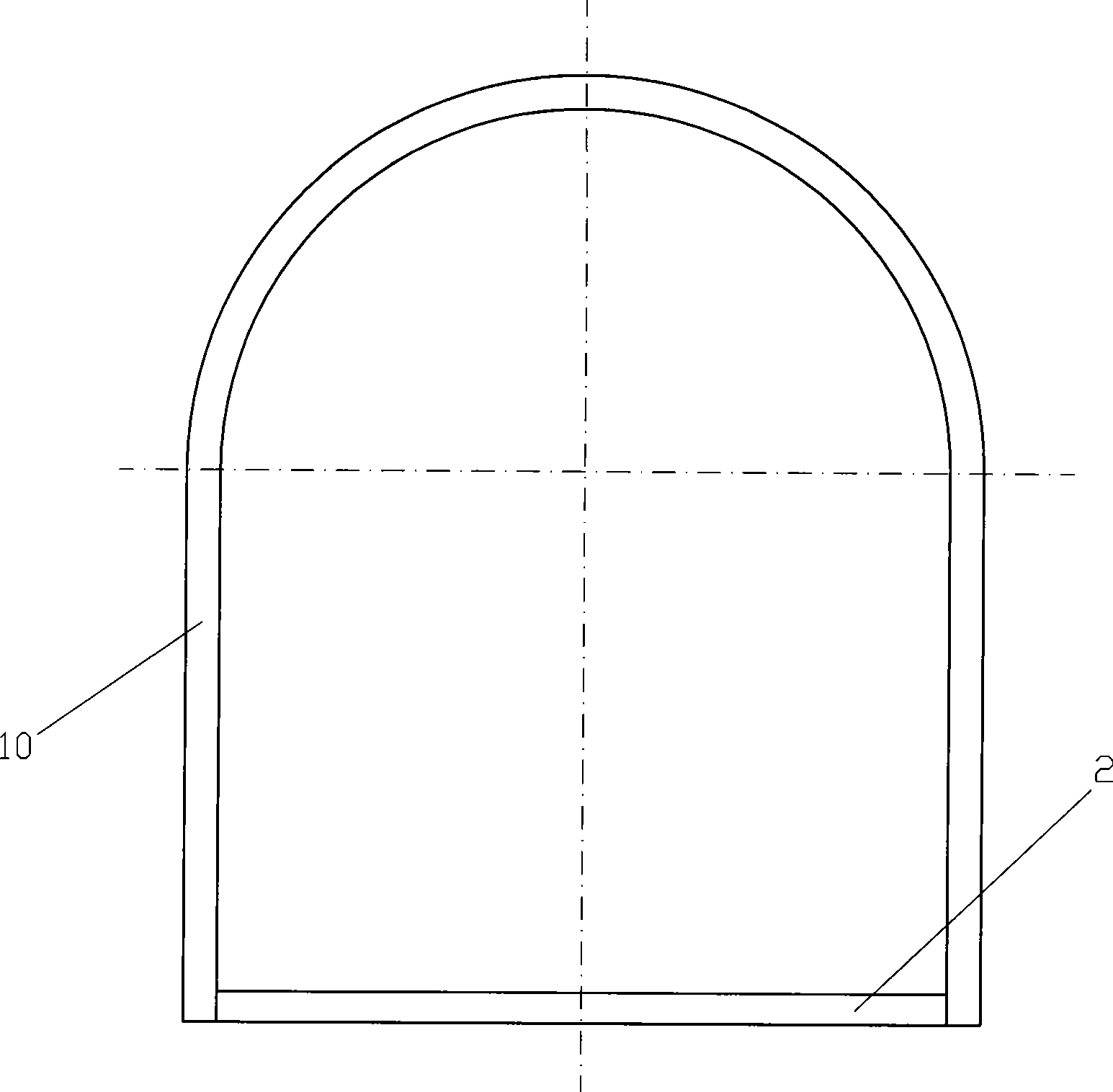
[0026] Embodiment one: if Figure 1 to Figure 7 Shown, the supporting plate 2 is fixed on the top of the column 1 fixed on the foundation, the generator 3 is fixed on the supporting plate 2, and the rotor shaft 27 of the generator 3 is supported by a magnetic suspension bearing (not shown in the figure); The outer circle of the upper part is socketed with the disk 4, and some electromagnets 6 are vertically fixed on its upper end face, all of the electromagnets 6 are on the same circle, and the coil 5 of the electromagnet 6 is connected to the power output terminal of the controller 29 with a wire 28; The upper end of the rotor shaft 27 is fixed to the axially magnetized permanent magnetic disk 24 and induction disk 25 sequentially in the axial direction, the permanent magnetic disk 24 and the induction disk 25 form the transmission disk 23, and the lower end surface of the induction disk 25 is parallel to the upper end surface of the electromagnet 6. A gap; the arched ring 10 ...

Embodiment 2

[0027] Embodiment two: if Figure 8 Figure 9 As shown, the following changes are made to Embodiment 1. The permanent magnetic coil 7 and the collar 8 of the wind wheel 9 can also be replaced by a radially magnetized permanent magnetic coil 35, and the permanent magnetic disc 24 of the transmission disc 23 is replaced by a permanent magnetic disc 33. The magnetic disk 33 is made up of a number of sector-shaped magnetic blocks that are magnetized alternately along the axial polarity or by a permanent magnetic disk partitioned along the circumferential direction and alternately magnetized along the axial polarity, and fixed on the bottom surface of the permanent magnetic disk 33 along the axial direction Magnetic disc 32, induction disc 31; pick bar 34 is fixed on the lower part of arched ring 10, speed measuring sensor 13 is installed on the pick bar 34, and the head of sensor 13 faces the limit portion of the upper end surface of permanent magnetic disc 33 and leaves a gap , ...


PUM


Abstract

The invention relates to a self-adjusting suspension wind power generation system. A supporting plate is fixed on the top end of an upright pole and a generator is fixed on the supporting plate. The rotor axis of the generator is supported by magnetic suspension bearing; a disc is sleeved and connected on the external circle of the upper part of the generator stator, a plurality of electromagnets are vertically fixed on the upper end surface of the stator, and the electromagnets are connected with a controller; a permanent magnetic disc and an inducting disc that are axially magnetized are fixedly connected on the upper end part of the rotor; an arch ring is fixed on the side surface of the supporting plate, and an inverted-T shaped axis is vertically fixed right under the top of the rotor axis; a connector is connected with the lower end of the inverted-T shaped axis through a thrust bearing and a radial bearing; the wind wheel consists of a radially magnetized permanent magnetic ring, a guide ring, blades and a ferrule, and is arranged on a horizontal axis, which is supported by a magnetic bearing connected with the connector, and the axes of the axis are perpendicular to the rotor axis of the generator; the wind wheel and the permanent magnetic disc drive the generator to generate power through a non-contact magnetic force; a rudder plate is connected with the left end face of the connector and the magnetic bearing; and the wind wheel or the permanent magnetic disc speed sensor are arranged on the generator and the speed sensor is connected with the controller. The wind power generation system is characterized by extremely high generator efficiency.

Description

technical field [0001] The invention relates to wind power generation technology, in particular to a self-adjusting suspension wind power generation system. Background technique [0002] Wind energy is an inexhaustible source of clean energy. People love it and have designed countless wind power generation devices, which are mainly composed of wind wheels and generators. In order to improve the power generation efficiency, various wind rotors and generators and combinations thereof have been developed, but these are not enough. Contents of the invention [0003] The invention designs a self-adjusting suspension wind power generation system, the purpose of which is to capture wind energy to the greatest extent and fully improve the efficiency of wind power generation. [0004] The present invention is realized according to the following technical solutions. [0005] Such as Figure 1 to Figure 7 Shown, the supporting plate 2 is fixed on the top of the column 1 fixed on th...

Claims


Application Information

Patent Timeline
IPC IPC(8): H02K51/00H02K7/09H02P17/00F16C32/04F03D9/00F03D9/25
CPCY02E10/725Y02E10/722Y02E10/72
Inventor 刘新广
Owner 刘新广
Why Eureka
Try Eureka