
Polarization-maintaining fiber coupler, preparation method thereof and all-fiber optical current sensor

A technology of current sensor and polarization-maintaining optical fiber, which is applied in the coupling of optical waveguide and other directions, and can solve the problems of unreliable main performance of the device

Active Publication Date: 2010-12-15
上海康阔光智能技术有限公司
View PDF5 Cites 0 Cited by
  • Summary
  • Abstract
  • Description
  • Claims
  • Application Information

AI Technical Summary

Problems solved by technology

[0003] The all-fiber current sensor using the traditional 3×3 polarization-maintaining fiber coupler also makes the main performance of the device unreliable due to the shortcomings of the traditional polarization-maintaining fiber coupler

Method used


Image

  • Polarization-maintaining fiber coupler, preparation method thereof and all-fiber optical current sensor
  • Polarization-maintaining fiber coupler, preparation method thereof and all-fiber optical current sensor
  • Polarization-maintaining fiber coupler, preparation method thereof and all-fiber optical current sensor

Examples


Embodiment Construction

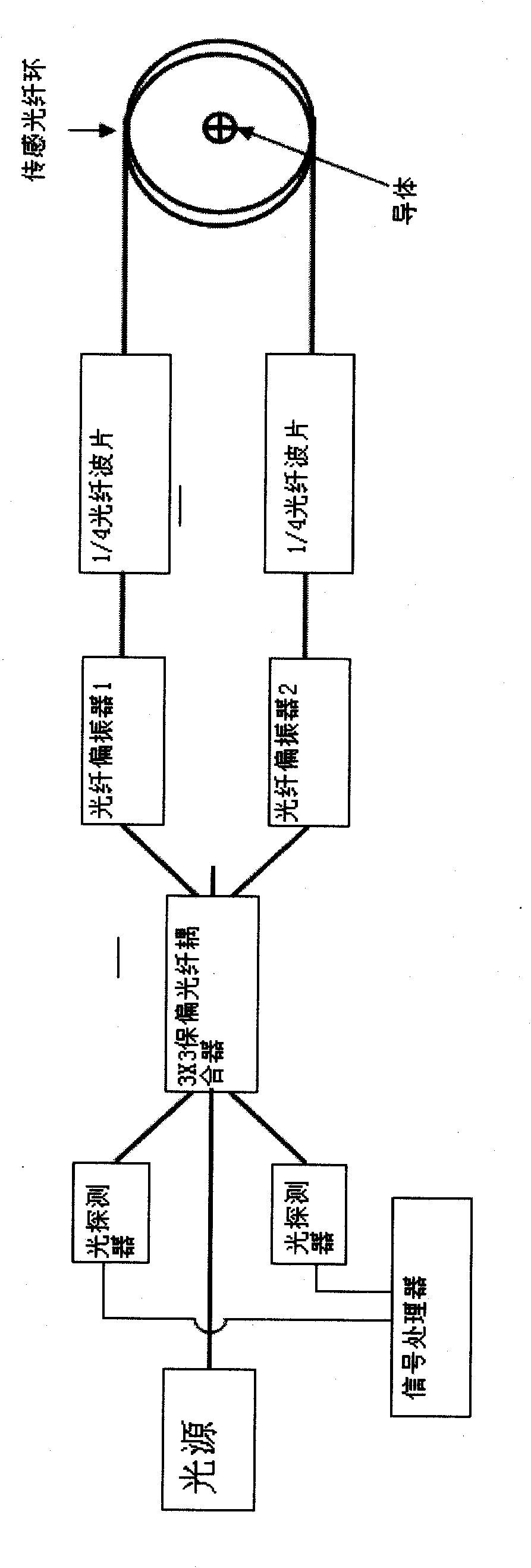
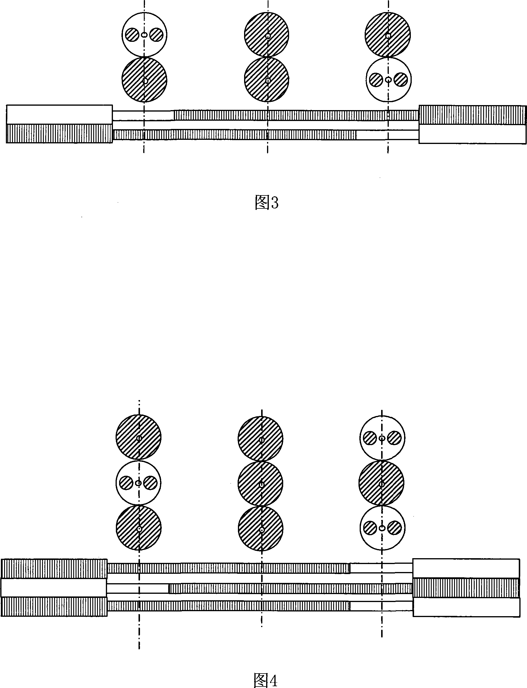
[0021] The polarization-maintaining fiber coupler of the present invention is developed based on the technology and characteristics of common single-mode fiber couplers, and the transmission characteristics of linearly polarized light in an ideal single-mode fiber without bending and perturbation. The main features of the polarization-maintaining fiber coupler of the present invention are: all of the coupling area is drawn from a single-mode fiber; the input end of the polarization-maintaining fiber coupler includes at least one polarization-maintaining fiber, and the output end directly connected with it is a single-mode fiber An optical fiber, the input end of the polarization-maintaining optical fiber coupler includes at least one single-mode optical fiber, and the output end directly connected to it is a polarization-maintaining optical fiber, and the polarization-maintaining optical fiber at the input end and the output end are respectively connected to the corresponding si...


PUM


Abstract

The invention discloses a polarization-maintaining fiber coupler. A coupling region of the polarization-maintaining fiber coupler is made of single-mode optical fibers, an input end of the polarization-maintaining fiber coupler at least contains a polarization-maintaining optical fiber, an output end which is directly communicated with the input end is one single-mode optical fiber, the input endof the polarization-maintaining fiber coupler at least contains one single-mode optical fiber, an output end which is directly communicated with the input end is the polarization-maintaining optical fiber, and the polarization-maintaining optical fibers of the input end and the output end are fused with the corresponding single-mode optical fibers in the coupling region respectively. A method forpreparing the polarization-maintaining fiber coupler comprises the following steps that: firstly, a heat sealer is used to prepare two-node optical fibers; secondly, the optical fibers are arranged and axially positioned according to the design requirement; and finally, a plurality of the single-mode optical fibers in the middle are fused and drawn into the coupling region. In the polarization-maintaining fiber coupler, the coupling region is formed by drawing the single-mode optical fibers, so a device has the characteristics of no sensitivity to the polarization and temperature environment,and the stability and the reliability of the device are greatly improved. The invention also discloses an all-fiber optical current sensor.

Description

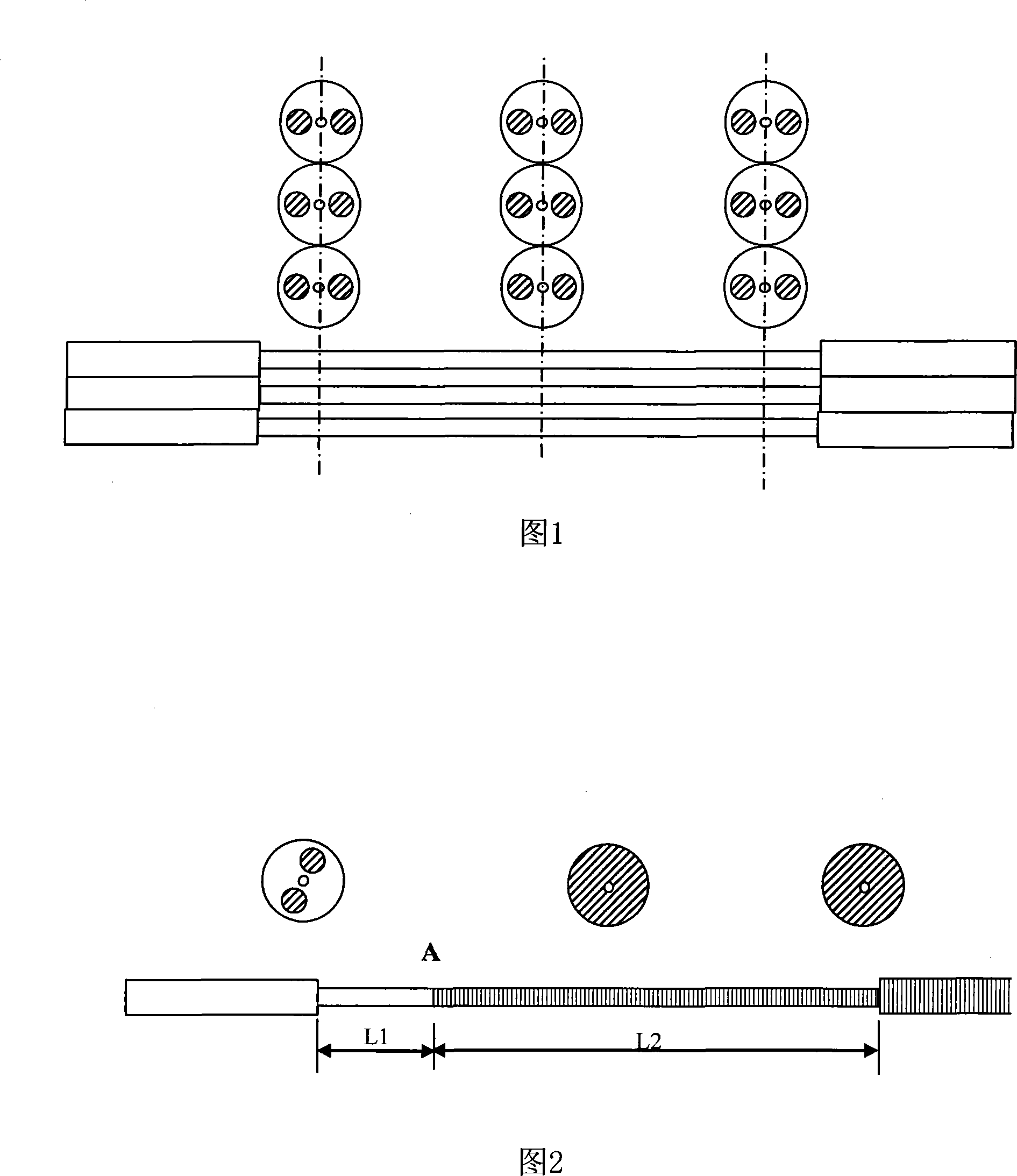
technical field [0001] The invention relates to a polarization maintaining optical fiber coupler and a preparation method thereof. The invention also relates to an all-fiber current sensor using the polarization-maintaining fiber coupler. Background technique [0002] Polarization-maintaining fiber couplers are widely used in various fields, especially in polarization-maintaining sensors. At present, most of the polarization-maintaining fibers are stress-type polarization-maintaining fibers. The main characteristics of the polarization-maintaining coupler made of this type of fiber are particularly sensitive to temperature. limits. Here we take 3×3 polarization-maintaining fiber coupling as an example (see figure 1 ), this device is made by using three polarization-maintaining optical fibers to be placed and positioned in a straight line, and then ensure that the optical fibers are parallel and close together, and then fused and tapered. Due to the difficulty of manufact...

Claims


Application Information

Patent Timeline
Patent Type & Authority Patents(China)
IPC IPC(8): G02B6/28
Inventor 黄勇
Owner 上海康阔光智能技术有限公司
Learn More