Kickback voltage suppression circuit

A technology for suppressing circuits and kickback voltages, applied in circuit devices, emergency protection circuit devices for limiting overcurrent/overvoltage, emergency protection circuit devices, etc., can solve problems such as increasing manufacturing costs

Inactive Publication Date: 2009-08-26
EUTECH MICROELECTRONICS
View PDF0 Cites 6 Cited by
  • Summary
  • Abstract
  • Description
  • Claims
  • Application Information

AI Technical Summary

Problems solved by technology

Therefore, the above-mentioned method of suppressing the kickback voltage requires corresponding selection of different Zener diodes (43) according to different system power supply (VCC) voltages and operating voltages of other components used in the system. ; Simultaneously, for different process technology, if will additionally provide the making of zener diode (43), will increase manufacturing cost

Method used


Image

  • Kickback voltage suppression circuit
  • Kickback voltage suppression circuit
  • Kickback voltage suppression circuit

Examples


Embodiment 1

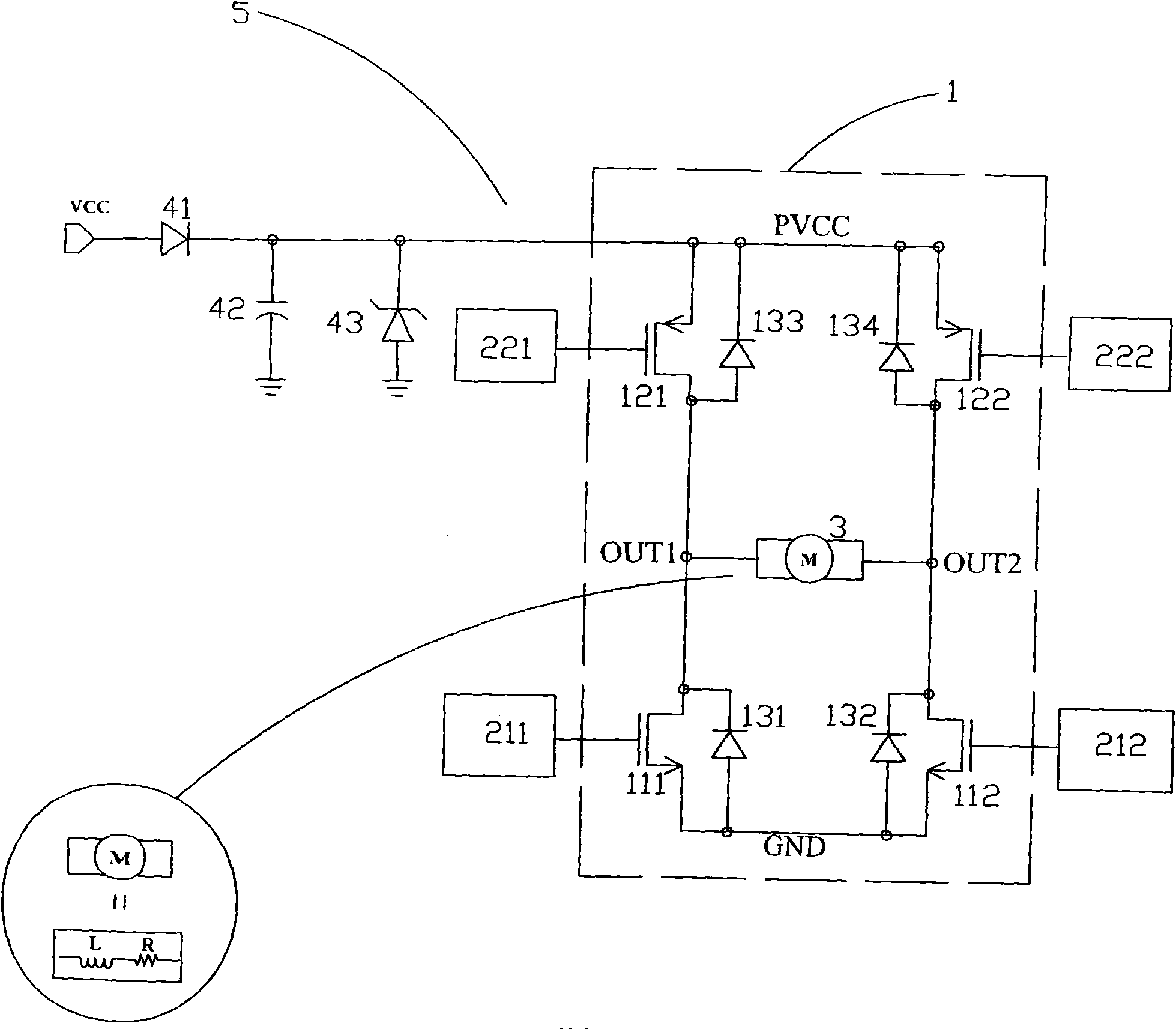
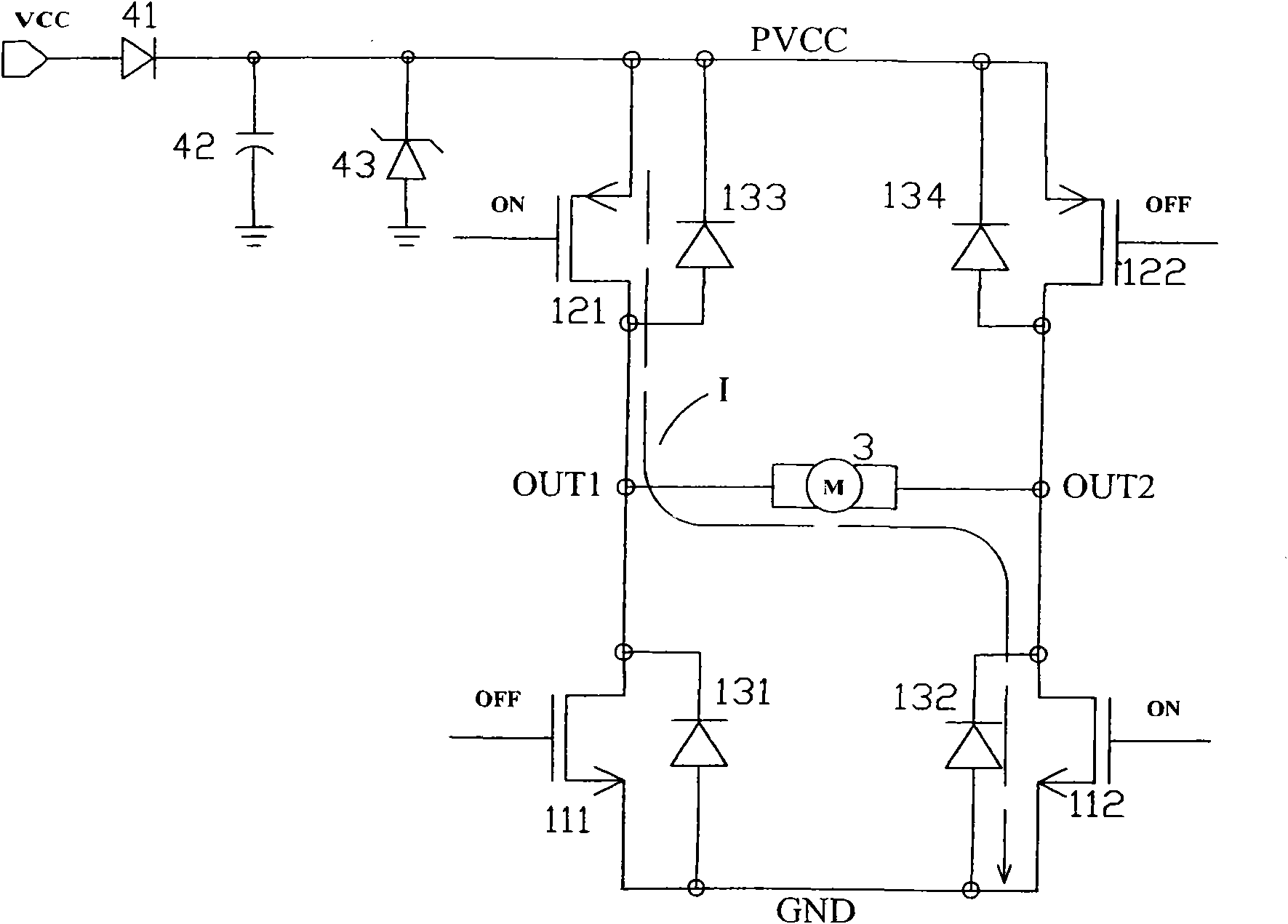
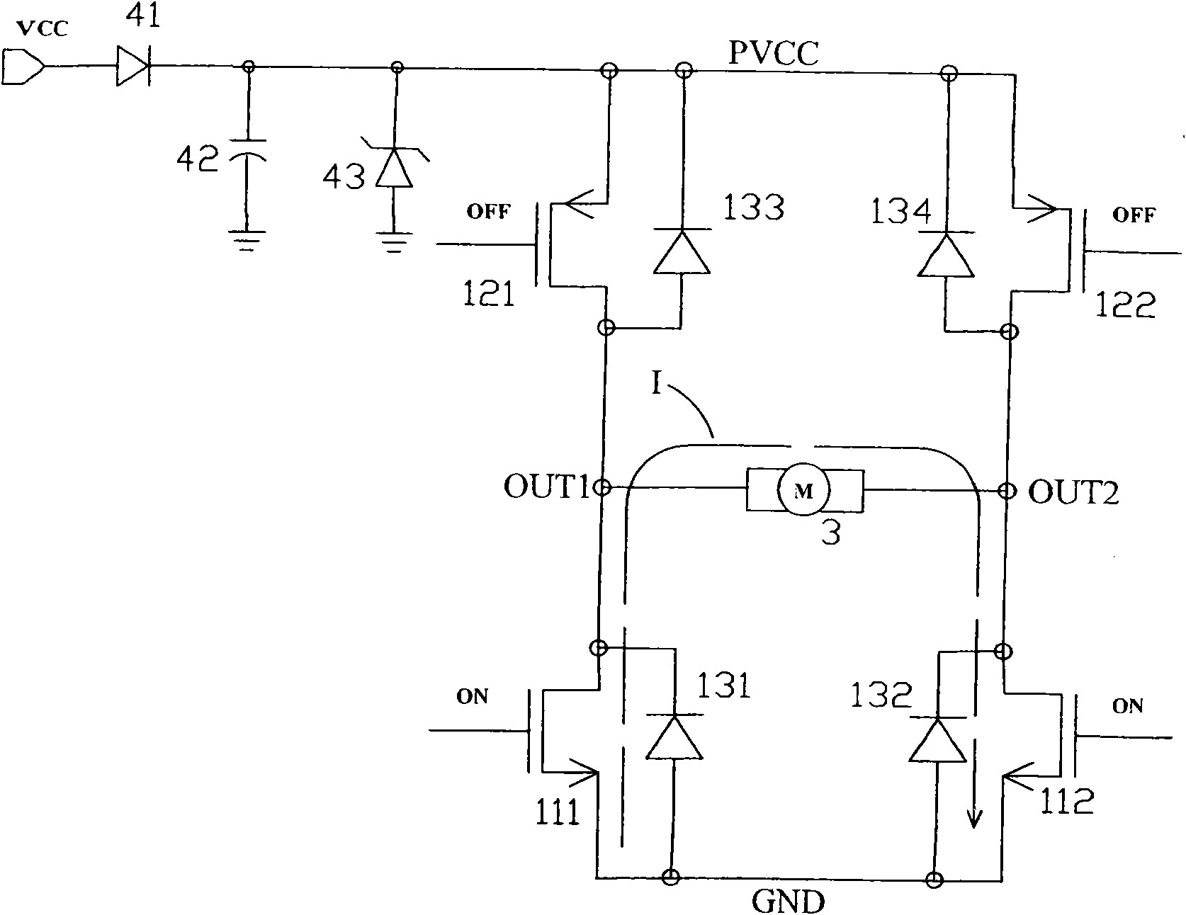
[0094] Example 1, please refer to Figure 5-6 , the kickback (kickback) voltage suppression circuit (5), including: a H-bridge (H-Bridge) power transistor group (1), two high-speed comparators (61) (62), two logic circuits (211) (212), two control circuits (221) (222); the H-Bridge power transistor group (1) is provided with four input system terminals (12P1) (12P2) (11P1) (11P2), two output drive terminals (OUT1) (OUT2), a power supply terminal (PVCC), a ground terminal (GND); these high-speed comparators (61) (62) are all provided with a positive input terminal (61P1) / (62P1), a negative input terminal (61P2) / (62P2) and an output terminal (61P3) / (62P3); these logic circuits (211)(212) are provided with two logic input terminals (211P1)(211P2) / (212P1)(212P2) 1. A logic output terminal (211P3) / (212P3); these control circuits (221)(222) are provided with a logic input terminal (221P1) / (222P1) and a logic output terminal (221P2) / (222P2).

[0095] The H-Bridge power transistor g...


PUM


Abstract

The invention provides a kickback voltage suppression circuit, which comprises an output stage driving power transistor serving as a current path, high-speed comparators for detecting a kickback voltage and a plurality of logic circuits. To reduce the area of the kickback voltage suppression circuit, the output stage driving power transistor serving as a current path can be realized by using an H-bridge power transistor group. When the difference of the output voltage of the H-bridge power transistor group and the voltage of a power supply end reaches a preset value, the output voltages of the compactors reverse to allow the related logic circuit to generate control signals to open or close the correspondingly connected power transistors. Thus, the current in an inductive load flows in a constant direction and is gradually used out.

Description

technical field [0001] The invention relates to a kickback voltage suppressing circuit, in particular to a kickback voltage suppressing circuit with high-speed circuit response and capable of reducing chip manufacturing area. Background technique [0002] see Figure 1-4 and Figure 11-12 , the current application of the kickback voltage suppression circuit (5) is mainly used in the driving system of the inductive load. When the current flow path in the inductive load is cut off suddenly, a kickback (kickback) voltage will be induced instantaneously, and the kickback (kickback) is suppressed by using the kickback (kickback) voltage suppression circuit (5) Voltage. [0003] Many inductive load drive systems, such as disc drive systems and fan motor drive systems, use a kickback voltage suppression circuit (5) mainly composed of an H-Bridge power transistor group (1) , the H-Bridge power transistor group (1) includes four power transistors (121) (122) (111) (112), four diod...

Claims


Application Information

Patent Timeline
Patent Type & Authority Applications(China)
IPC IPC(8): H02H7/20H02H7/10H02H9/04
Inventor 肖科孙江
Owner EUTECH MICROELECTRONICS
Why Eureka
Try Eureka