Passive motion-type exercise assistance device

An auxiliary device and passive technology, applied in sports accessories, passive exercise equipment, gymnastics equipment, etc., can solve problems such as inability to use, knee burden, etc., achieve the effect of improving symptoms, promoting sugar intake, and high rehabilitation effect

Inactive Publication Date: 2009-08-26
PANASONIC CORP
View PDF2 Cites 11 Cited by
  • Summary
  • Abstract
  • Description
  • Claims
  • Application Information

AI Technical Summary

Problems solved by technology

However, since walking is simulated, the same level of load is placed on the kne

Method used


Image

  • Passive motion-type exercise assistance device
  • Passive motion-type exercise assistance device
  • Passive motion-type exercise assistance device

Examples


Embodiment approach 1

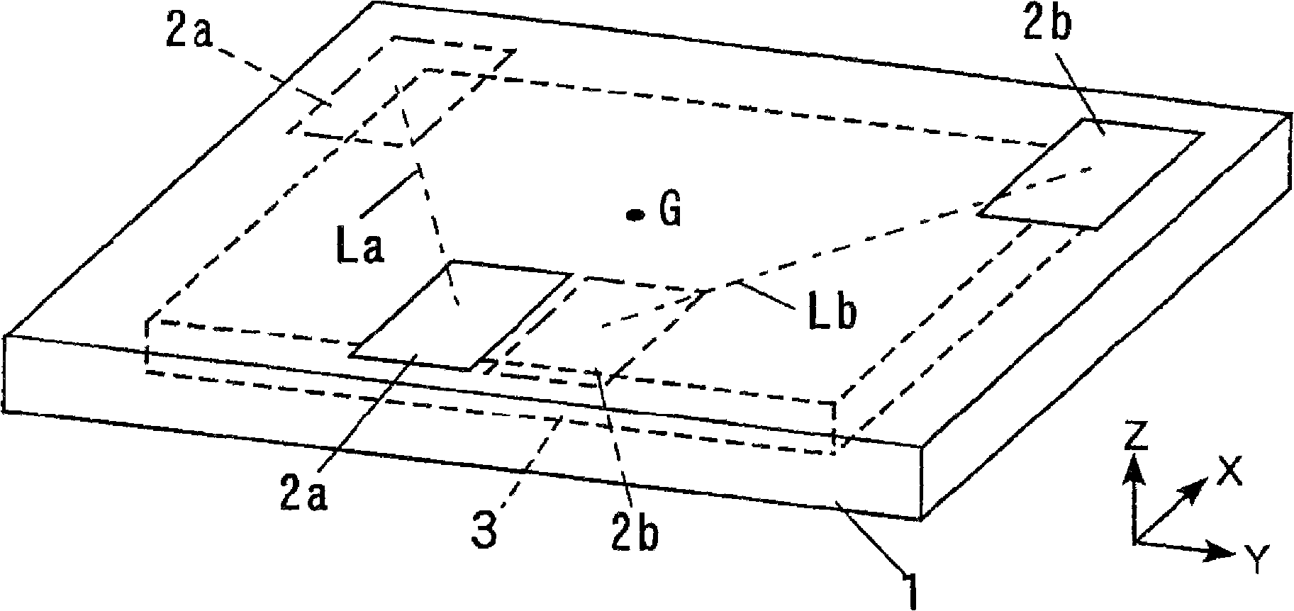
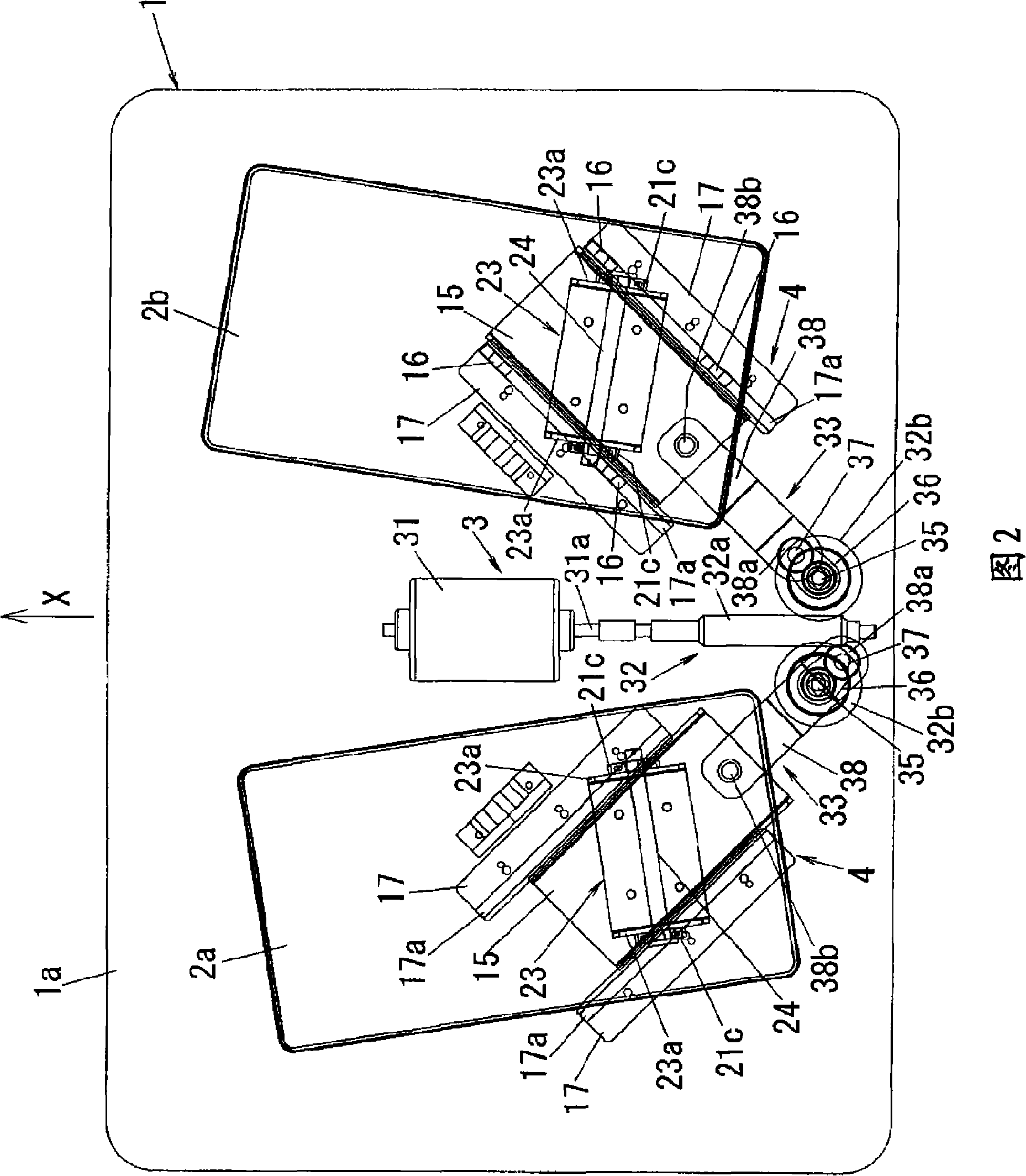
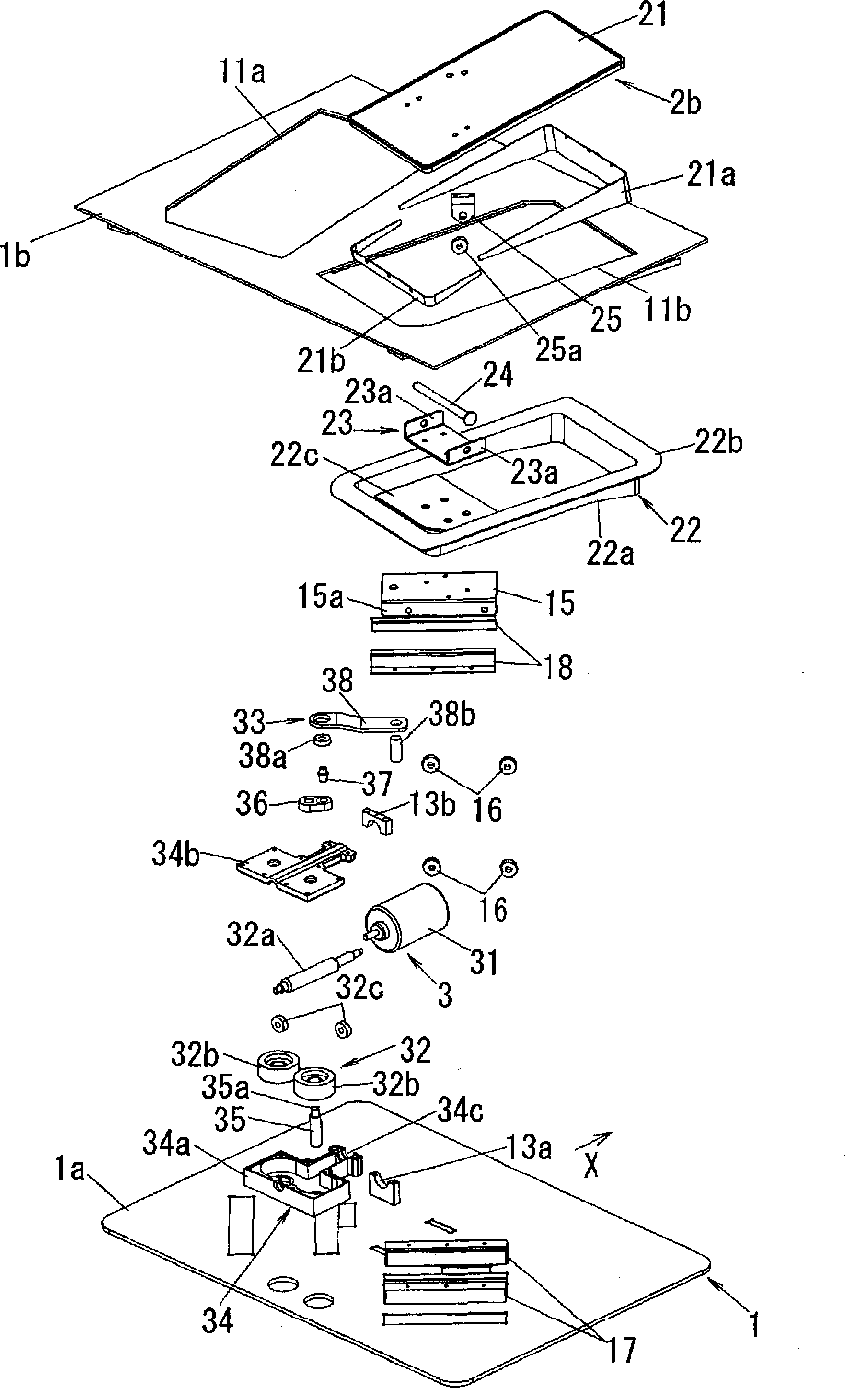
[0062] As the basic structure of the present invention, it will be described figure 2 and image 3 composition shown. In the present embodiment, the configuration in which it is placed on the floor and used is exemplified, but a configuration in which it is buried and used under the floor may also be adopted. A configuration fixed at a fixed position, or a configuration movable in position can be appropriately selected. In addition, although the user can sit and use the device described below, the original intention is that the user basically uses it in a standing state.

[0063] In this embodiment, if figure 2 and image 3 As shown, a bottom plate 1a for installation on the floor is provided. Although the illustrated bottom plate 1a is rectangular, the outer peripheral shape of the bottom plate 1a is not particularly limited. Hereinafter, for simplicity of description, it is assumed that the upper surface of the base plate 1a is parallel to the floor surface in a stat...

Embodiment approach 2

[0147] In Embodiment 1, the left footrest 2a and the right footrest 2b move in opposite phases to each other in the front-back direction so that the position of the user's center of gravity does not move back and forth, but when the user's center of gravity moves back and forth, The reflex nervous system will work to keep the body from tipping over, so the muscle groups used to keep the body from tipping over (such as the latissimus dorsi, psoas, iliopsoas) will be stimulated.

[0148]The present embodiment realizes this effect, and it adopts the following structure, that is, the left foot support platform 2a and the right foot support platform 2b are not moved in opposite phases in the front-rear direction, but with an appropriate phase difference other than 180 degrees. to move. The phase difference may be 0 degree, and in this case, the left footrest 2a and the right footrest 2b move back and forth simultaneously. When the phase difference is not 180 degrees, acceleration ...

Embodiment approach 3

[0150] In Embodiment 1, the imitation protrusion 25 is protrudingly provided on the lower surface of the foot rest plate 21, and the imitation protrusion 25 moves on the guide surface 14 provided on the bottom plate 1a, whereby the left foot support platform 2a and the right foot support platform 2b The angle varies around the axis Ay in the y direction, but in this embodiment, as Figure 20 As shown, it is provided with: a first driving part 33a, which makes the representative points of the left foot support 2a and the right foot support 2b slide along the upper surface of the bottom plate 1a after the driving force is separated by the system separation part 32; Two driving parts 33b, which change the angles of the left footrest 2a and the right footrest 2b around the axis Ay in the y direction. The first driving part 33a and the second driving part 33b have Figure 21 composition shown. Here, the transmission path for transmitting the driving force from the worm wheel 32b ...


PUM


Abstract

A passive motion-type exercise assistance device in which a left foot support table (2a) and right foot support table (2b), on which left and right feet of the user are respectively placed, are provided on the upper surface of a housing (1) installed on a floor. The left and right foot support tables (2a, 2b) are associated with each other by a drive device (3) and positionally moved. As the drive device (3) changes the positions in the front-rear direction of the left and right foot support tables (2a, 2b), it reciprocates the support tables (2a, 2b) so that their positions in the left-right direction are changed and, also, it moves the support tables (2a, 2b) so that the distance between them in the left-right direction at the front end positions in the movement loci (La, Lb) of representative points of the support tables (2a, 2b) is greater than the distance in the left-right direction of the points at their rear end positions.

Description

technical field [0001] The present invention relates to a passive exercise assisting device that is mainly used by a user while standing and stretches and contracts leg muscles based on passive motion. Background technique [0002] Conventionally, various passive exercise assisting devices have been proposed. These devices are based on passive exercise in which the user does not exert physical strength spontaneously but applies external force to the user's body to expand and contract muscle groups to obtain exercise effects. Among such passive exercise assisting devices, there are known devices that expand and contract the muscles associated with the joints by flexing and extending the joints, and those that expand and contract the muscles by the reflection of the nervous system by applying stimulation to the body. installation. [0003] In addition, there are various postures during use depending on the muscle groups that need to be stretched. For the device that the user ...

Claims


Application Information

Patent Timeline
IPC IPC(8): A61H1/02A63B23/04
CPCA61H2203/0406A61H1/0237A61H1/005A61H1/0266A63B23/04A61H2201/1427A61H2201/0119A61H2205/10
Inventor 越智和弘四宫叶一小泽尚久后藤孝夫斋藤笃裕菅井春夫
Owner PANASONIC CORP
Why Eureka
Try Eureka