Device for optimizing the feed function of the ring gear of a differential with regard to maximum volume flow rate

一种盘形齿轮、体积流量的技术,应用在传动装置零件、齿轮润滑/冷却、皮带/链条/齿轮等方向,能够解决输送量减小、没有公开输送功能等问题,达到输送功能优化的效果

Inactive Publication Date: 2009-08-26
ZF FRIEDRICHSHAFEN AG +1
View PDF0 Cites 4 Cited by
  • Summary
  • Abstract
  • Description
  • Claims
  • Application Information

AI Technical Summary

Problems solved by technology

In this way, an oil flow is formed around the rotating ring gear, which, however, forms a vortex due to the open design of the differential, so that the usable delivery volume is disadvantageously significantly reduced; nothing is known from the prior art for targeted use. The optimized ring gear with respect to the conveying function of the maximum volume flow

Method used


Image

  • Device for optimizing the feed function of the ring gear of a differential with regard to maximum volume flow rate
  • Device for optimizing the feed function of the ring gear of a differential with regard to maximum volume flow rate

Examples


Embodiment Construction

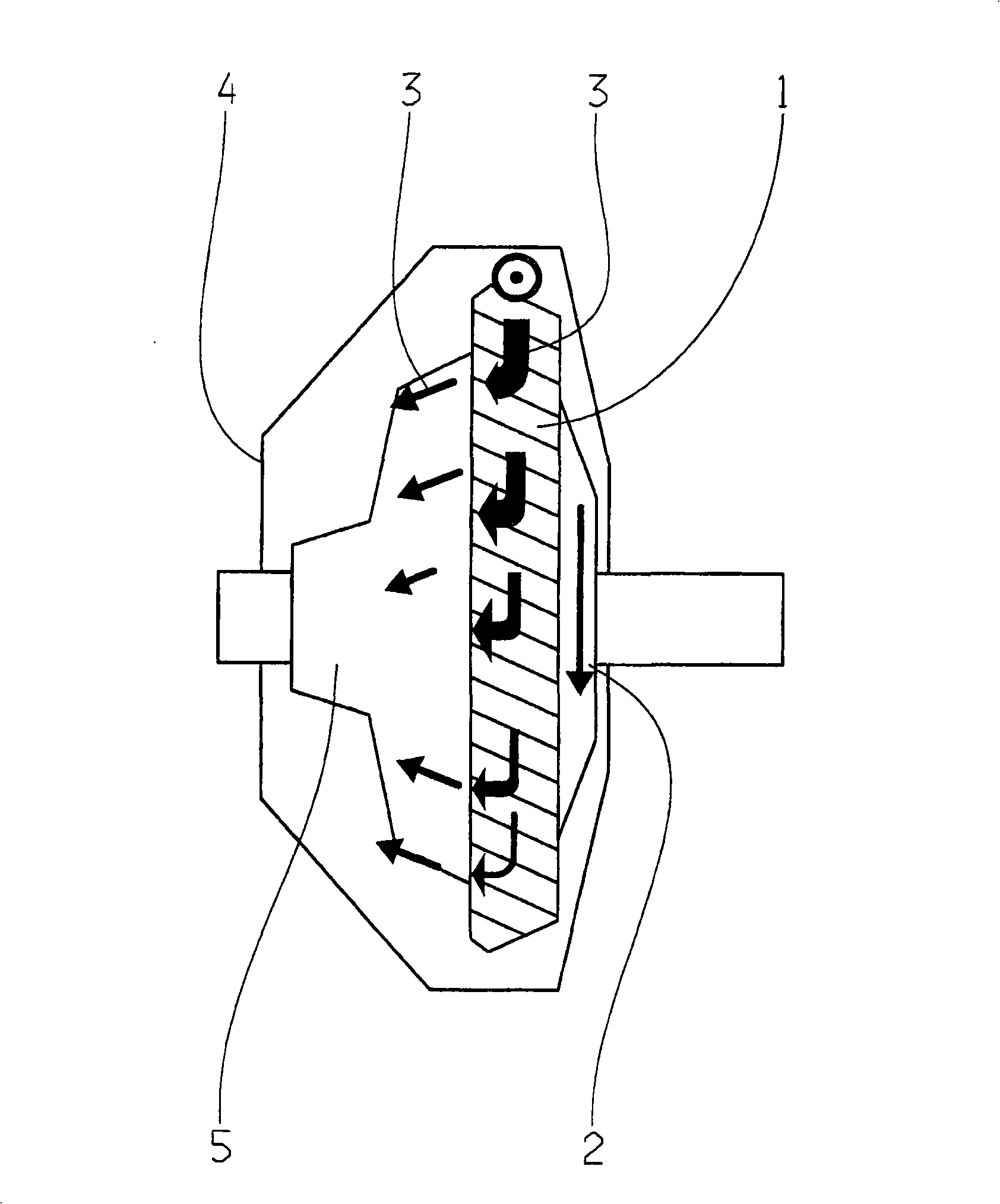
[0011] exist figure 1 A differential is shown which contains a ring gear 1 which rotates in the direction of the arrow 2 in the drawing. The differential case and differential cover are denoted with 5 and 4 respectively. The oil is entrained by the ring gear toothing in the circumferential direction due to the rotational movement of the ring gear 1 and is discharged at the speed of the ring gear 1 . The oil flow formed here is indicated by arrow 3 in the drawing. As can be seen from the figure, the oil flow is swirled due to the open design of the differential, so that the available delivery rate is significantly reduced.

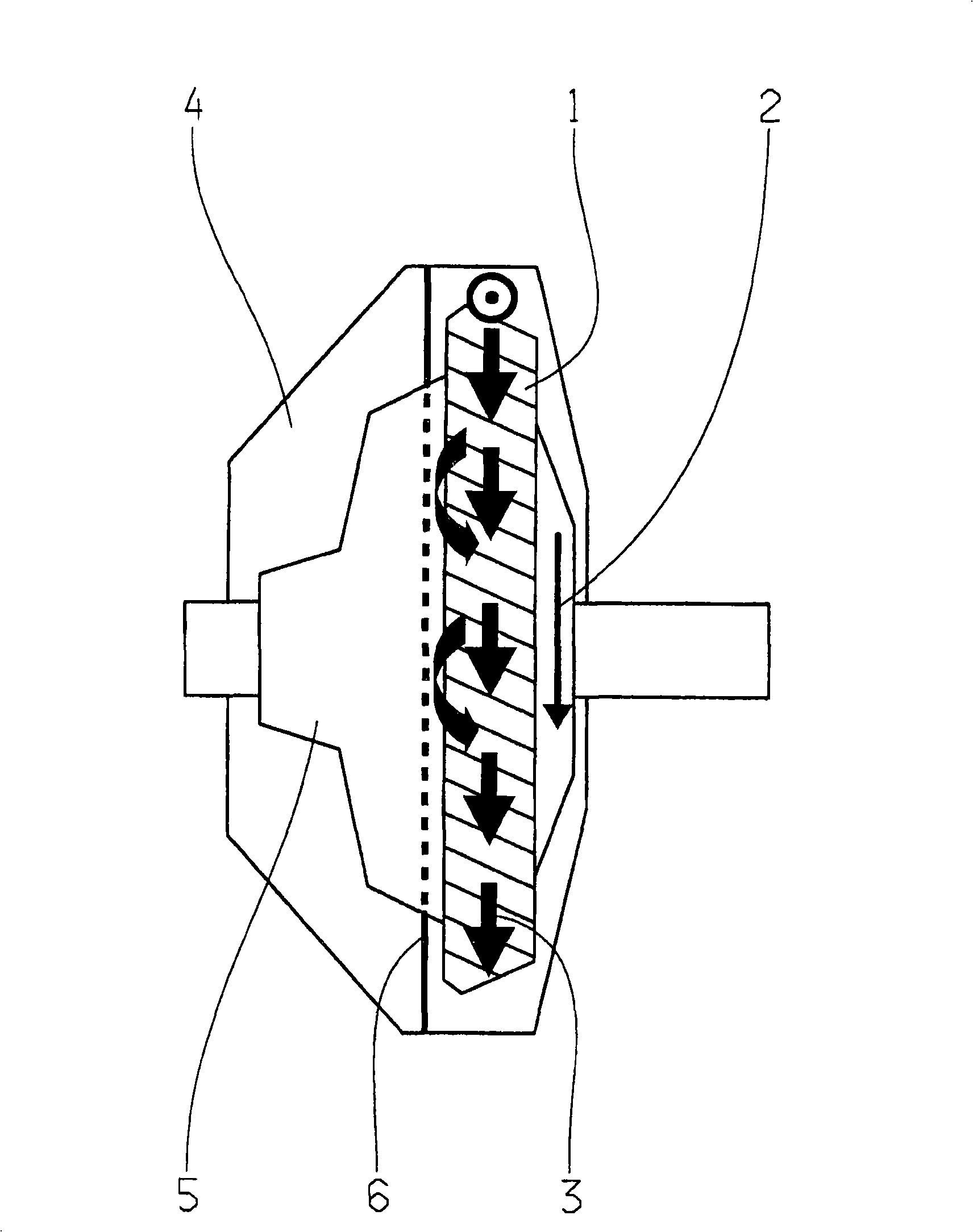
[0012] In order to solve this problem, it is proposed according to the invention that, viewed in the axial direction, next to the ring gear 1 on the side of the ring gear facing the differential carrier 5 and coaxially with the ring gear with the smallest possible A spacer 6 is mounted at a distance, which serves as an oil wiper ring and which seals with...


PUM


Abstract

The invention relates to a device for optimizing the feed function of the ring gear of a differential with regard to maximum volume flow rate, which comprises an annular disk (6) which is arranged, as viewed axially, adjacent to the ring gear (1) at its side facing toward the differential cage (5) and coaxially with respect to the ring gear (1), and which serves as a scraper ring.

Description

technical field [0001] The invention relates to a device according to the preamble of claim 1 for optimizing the delivery function of a ring gear of a differential with respect to a maximum volume flow. Background technique [0002] It is known from the prior art to use the pumping action of the ring gears of the differential in transmissions with integrated axle drives to circulate an oil volume. The oil is entrained in the circumferential direction by the toothing of the ring gear and is discharged at the assumed speed of the ring gear. In this way, an oil flow is formed around the rotating ring gear, which, however, forms a vortex due to the open design of the differential, so that the usable delivery volume is disadvantageously significantly reduced; nothing is known from the prior art for targeted use. An optimized ring gear with respect to the conveying function of the maximum volumetric flow. Contents of the invention [0003] It is an object of the present invent...

Claims


Application Information

Patent Timeline
Patent Type & Authority Applications(China)
IPC IPC(8): F16H57/04
CPCF16H57/0483F16H57/0423F16H57/0434
Inventor R·阿尔法特M·格吕克S·雅布斯
Owner ZF FRIEDRICHSHAFEN AG
Why Eureka
Try Eureka