Rotatable grip for a photographic camera

A technology for rotating a handle and a camera, which is applied in the field of cameras and can solve problems such as unfavorable operating performance, excessive locking device play, and influence.

Inactive Publication Date: 2009-08-26
KODAK IL
View PDF2 Cites 0 Cited by
  • Summary
  • Abstract
  • Description
  • Claims
  • Application Information

AI Technical Summary

Problems solved by technology

However, a drawback in this construction is that the play of the locking device is too great, thus having an adverse effect on the operability

Method used


Image

  • Rotatable grip for a photographic camera
  • Rotatable grip for a photographic camera
  • Rotatable grip for a photographic camera

Examples


Embodiment Construction

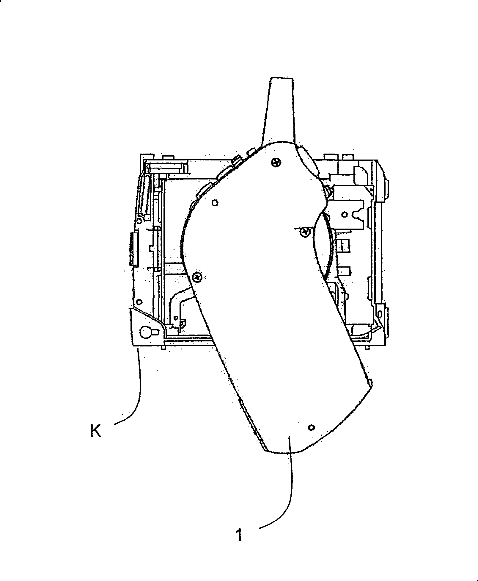
[0016] exist figure 1 The field of application of the device according to the invention is shown in the illustrated embodiment. Its application is not limited to this camera. Neither is the invention limited to the specific measurements and dimensional relationships of the shapes shown in the drawings.

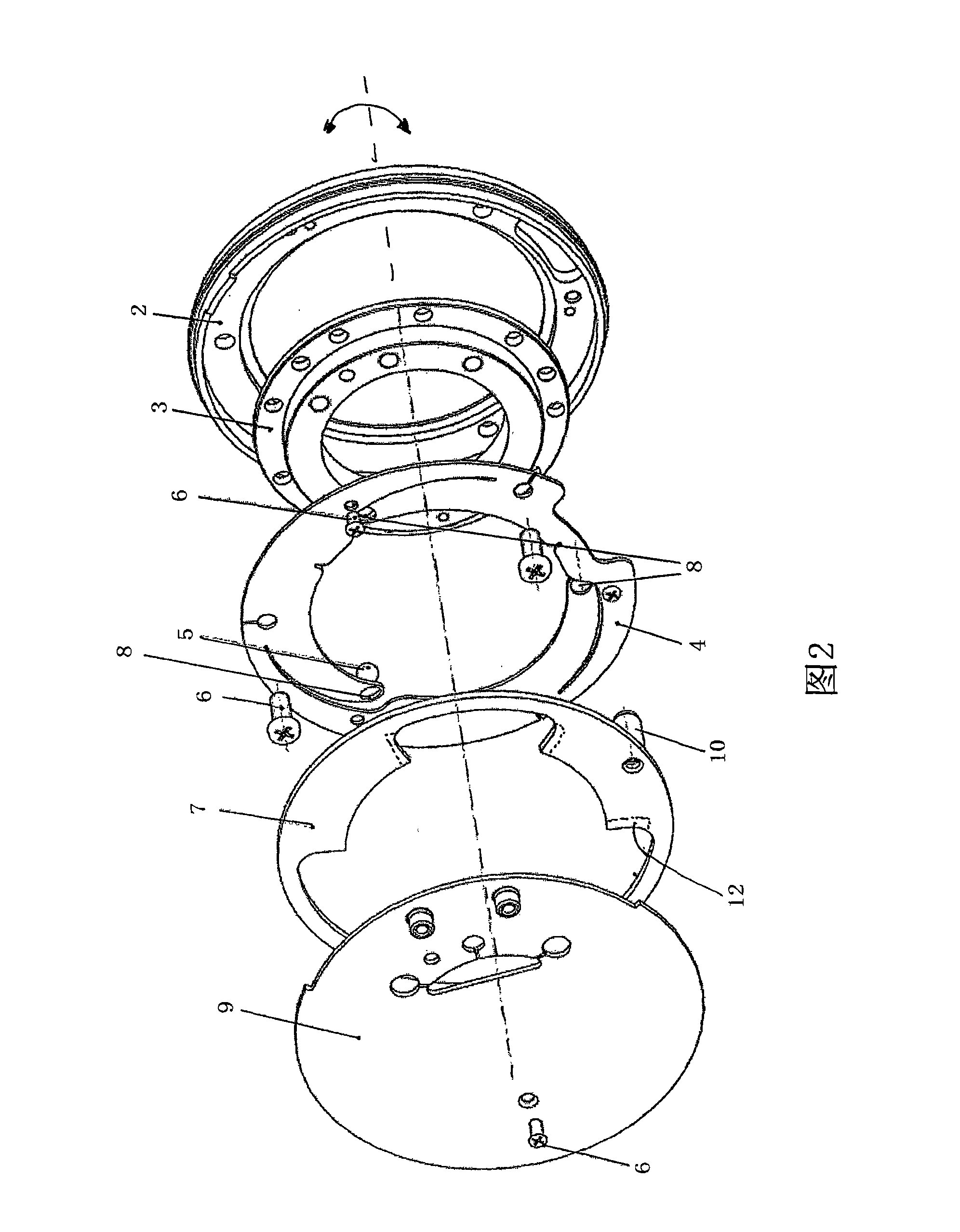
[0017] figure 2 The structure of the locking mechanism is shown with an exploded view. The structure according to the invention allows absolutely no play and no rattling noise when screwed together. Arrows indicate rotational movement in the blocking and non-blocking directions of the handle.

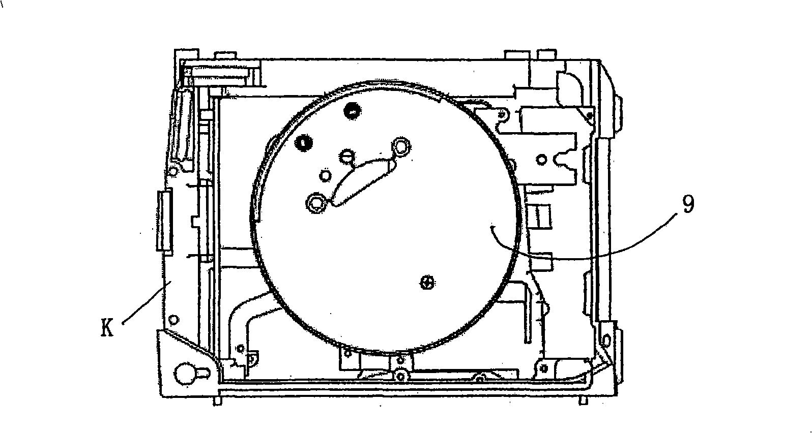
[0018] Figure 3 to Figure 5 The locking mechanism on the camera housing is shown in turn in side view (handle not shown) with the cover ( image 3 ), the locking mechanism does not have a cover ( Figure 4 ), the locking mechanism does not have a cover and bezel ( Figure 5 ).

[0019] Image 6 Arrangement with handle and exploded view are shown. A slide 11 is fastened behi...


PUM


Abstract

A rotatable grip for cameras consists, according to the invention, of a play-free latching mechanism comprising, arranged one after the other, a bearing ring (2), a grip plate (3), a leaf spring (4) and steel balls (5) deposited therein with a form fit. According to the invention, leaf spring (4) and bearing ring (2) are connected to the base body of the camera by the balls being pushed into the holes (8) of the grip plate (3) by the leaf spring (4). The connection is preferably effected with the aid of a screw-connection (6). Due to the rotation of the grip (1), the balls (5) are pushed out of the hole of the grip plate (3) counter to the spring force. The grip (1) is pivoted until the balls (5) latch in the desired position into the holes of the selected latch position. In order to secure the selected latch position in the long term, a blocking plate (7) which can pivot about the axis of rotation of the grip plate (3) can prevent the latch balls (5) from moving.

Description

technical field [0001] The invention relates to a rotatable handle for cameras, in particular for reflex cameras. The grip according to the invention is connected to the base body of the camera by means of a locking mechanism. Background technique [0002] Cameras equipped with rotatable handles are known, with the rotatable handles having a wide variety of configurations. In US Patent No. 4,405,223 a reflex camera with a pistol grip is described, wherein the grip is secured by means of a cage structure. In this case, the pivoting ability is greatly restricted and leads to loosening of the retaining element during use. From DE19534231 is known a pivoting holding handle structure in a reflex camera. However, a drawback in this construction is that the play of the locking means is too great, thus having a negative effect on the operability. Contents of the invention [0003] It is an object of the present invention to provide a camera with a housing and a rotatable handl...

Claims


Application Information

Patent Timeline
Patent Type & Authority Applications(China)
IPC IPC(8): G03B17/56
CPCG03B17/56G03B17/563Y10T292/0922
Inventor 赫尔穆特·科切尔
Owner KODAK IL
Why Eureka
Try Eureka