Crankshaft type dynamic baby carrier
A crankshaft and baby carriage technology, applied in the field of crankshaft dynamic baby carriages, can solve problems such as boredom and lack of fun, and achieve the effect of enhancing fun, enhancing sitting fun, and better effects
- Summary
- Abstract
- Description
- Claims
- Application Information
AI Technical Summary
Problems solved by technology
Method used
Image

Examples
Embodiment 1
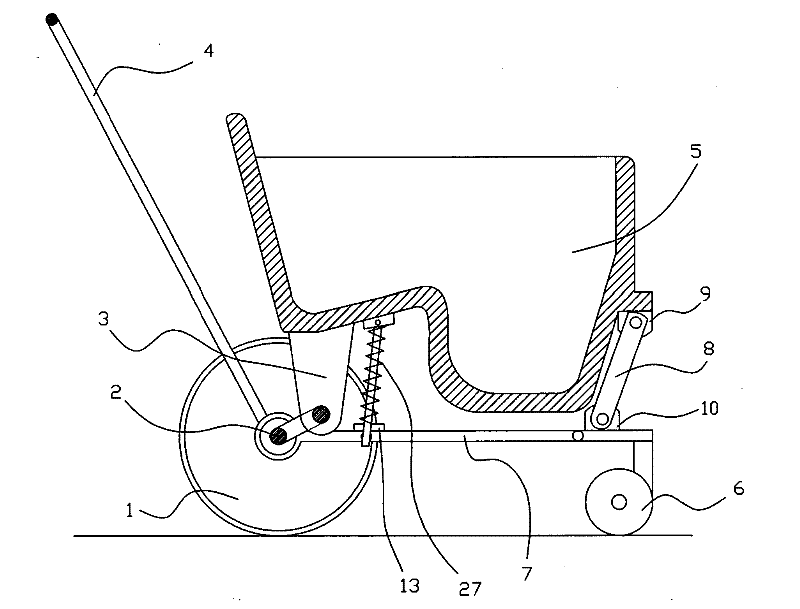
[0021] Embodiment one: if figure 1 , 2 As shown, the crankshaft-type dynamic baby carriage includes a rear wheel 1, a crankshaft 2, a connecting rod 3, a push handle 4, a carrier 5, and a front wheel 6.
[0022] The middle part of the crankshaft 2 is concave, and the two ends are connected with the two rear wheels 1. One of the rear wheels is fastened to the crankshaft 2. When pushing, the crankshaft 2 is driven to rotate, and the other rear wheel is rotatably matched with the crankshaft 2 to facilitate the baby carriage. turn.
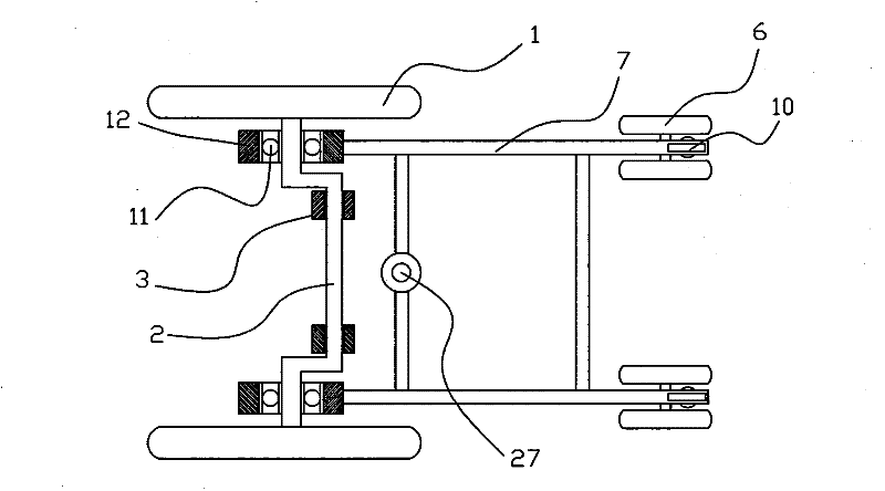
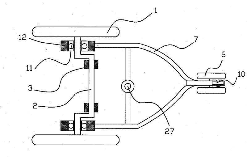
[0023] The undercarriage 7 is arranged below the carrier body 5 , the rear end of the undercarriage 7 is fixed on the bearing seat 12 , and the bearing 11 is installed between the bearing seat 12 and the crankshaft 2 . The lower part of the front end of the underframe 7 is equipped with the steering front wheel 6, and the upper part of the front end is provided with a lug 10 with holes; .
[0024] The lower end of push handle 4 is fixed on the rea...
Embodiment 2
[0027] Embodiment two: if image 3 As shown, the baby carriage is a three-wheel structure type baby carriage, and other contents are the same as the first embodiment.
Embodiment 3
[0028] Embodiment three: as Figure 4 As shown, the crankshaft 2 is in the shape of a double crank, and the connecting rod 3 is connected to the concave portion of the crankshaft 2, and other contents are the same as in the first embodiment.
[0029] Embodiment four: if Figure 5 As shown, the two rear wheel structures of the present embodiment adopt the roller clutch. The two ends of the crankshaft 2 each utilize a key 26 to affix the clutch inner ring 20 of the clutch. The clutch inner ring 20 is evenly distributed with several gaps 21 along the outer circumference, and a spring hole is arranged on the vertical surface of the gap 21, and a spring is built in the spring hole. 24 and push rod 22, the outer end of push rod 22 withstands the roller 23 on the gap 21, and roller 23 can roll on the gap 21. There is a rotation gap between the clutch inner ring 20 and the clutch outer ring 25, and the clutch outer ring 25 is fixedly connected with the rear wheel 2.
[0030] When t...
PUM
 Abstract
Description
Claims
Application Information