Method and device for liquid density measurement

A liquid density and measuring device technology, which is applied to determine the specific gravity and other directions by measuring the pressure difference, can solve the problems of difficult to meet the needs, low accuracy and efficiency, and achieve the effect of strong practicability, simple implementation and reliable measurement process

Inactive Publication Date: 2011-01-19
HUAZHONG UNIV OF SCI & TECH
View PDF0 Cites 0 Cited by
  • Summary
  • Abstract
  • Description
  • Claims
  • Application Information

AI Technical Summary

Problems solved by technology

In the measurement with relatively high accuracy requirements, this measurement method with relatively low accuracy and efficiency is obviously difficult to meet the needs

Method used


Image

  • Method and device for liquid density measurement
  • Method and device for liquid density measurement
  • Method and device for liquid density measurement

Examples


Embodiment Construction

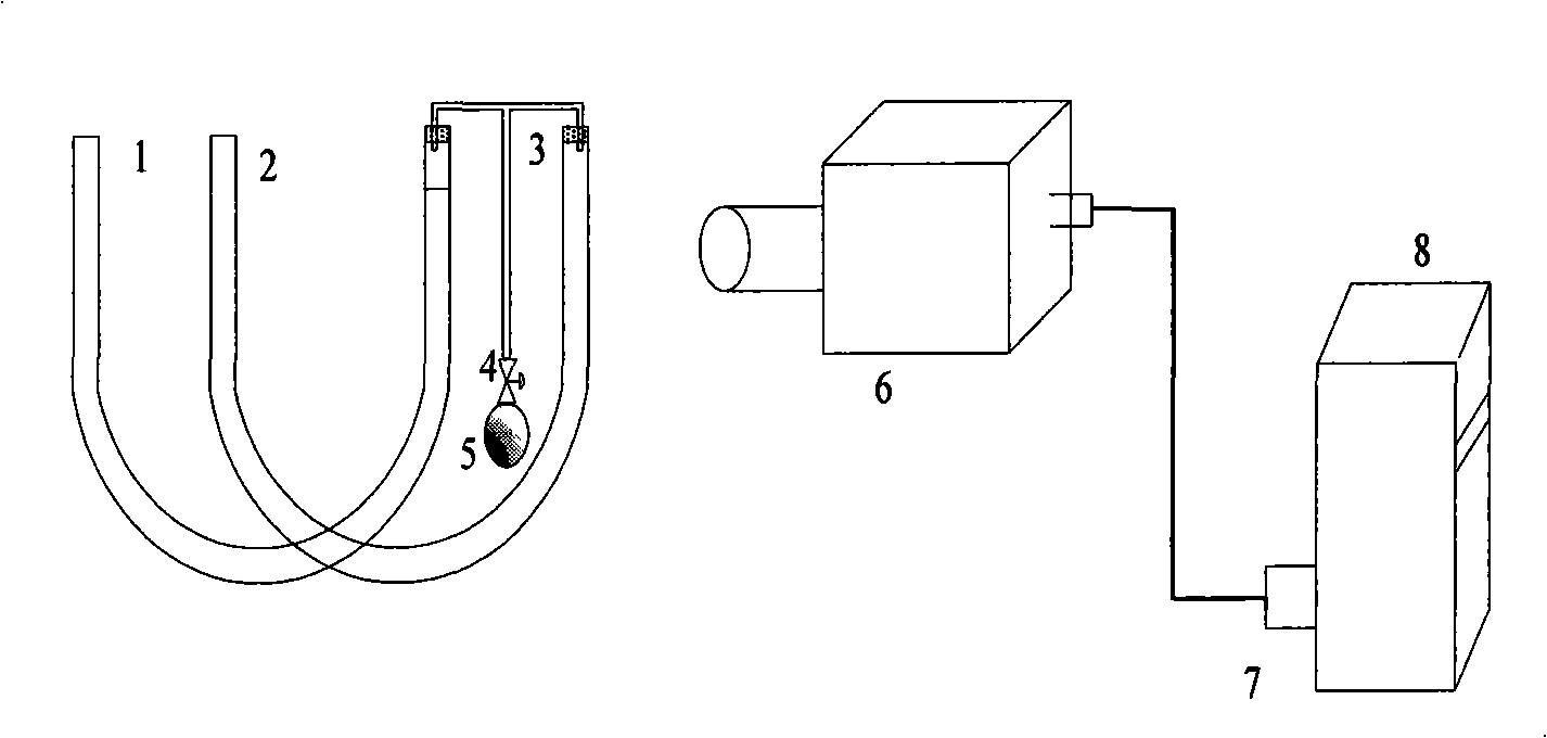
[0017] Device of the present invention and realization principle are:

[0018] Such as figure 1 As shown, the left port of the first U-shaped pipe 1 and the second U-shaped pipe 2 are connected to the atmosphere, and the right port is connected by a three-way pipe 3 after adding a rubber stopper. A scale mark is engraved on the first U-shaped tube 1 as the standard liquid level. The first U-shaped pipe 1 and the second U-shaped pipe 2 are placed side by side. The other end of the tee pipe 3 is connected to the rubber ball 5 through the control valve 4 . The camera 6 adopts a camera, and the camera is aimed at the right end of the first U-shaped pipe 1 and the second U-shaped pipe 2, and the computer 8 is connected with the camera by an image acquisition card 7.

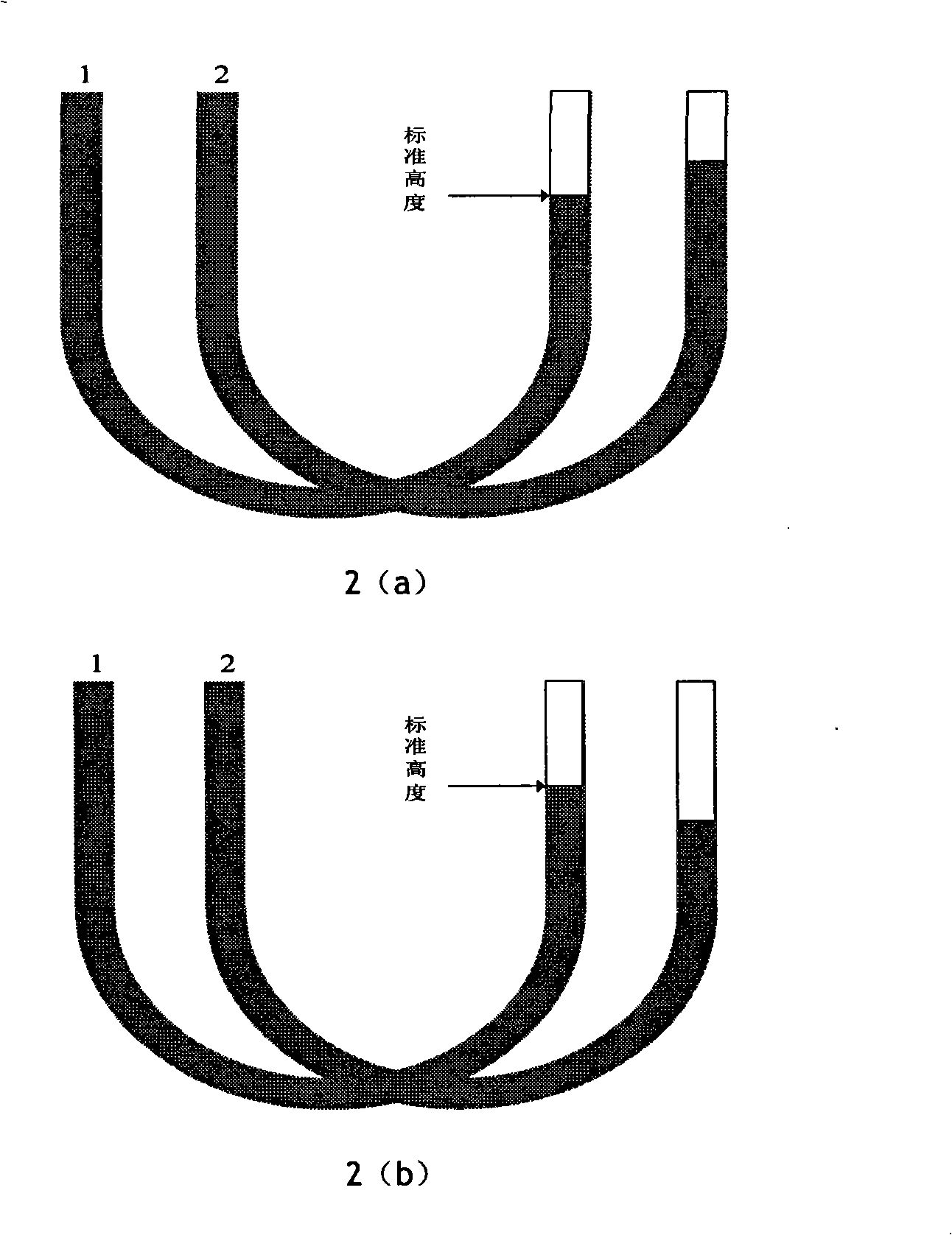
[0019] During work, the first U-shaped tube 1 is filled with the liquid to be tested, and the second U-shaped tube 2 is filled with the standard liquid (such as water). When air is filled into the first U-shaped p...


PUM


Abstract

The invention discloses a method for liquid density measurement. The method comprises the following steps: arranging two U-shaped pipes in parallel; filling the first U-shaped pipe with a liquid to beThe invention discloses a method for liquid density measurement. The method comprises the following steps: arranging two U-shaped pipes in parallel; filling the first U-shaped pipe with a liquid to beability, and improve the working efficiency and the measurement reliability.operability, and improve the working efficiency and the measurement reliability. of the first U-shaped pipe and the second U-shaped pipe which are connected with the three-way pipe, and is connected with a processor. The method and the device have simple realization and high oper of the first U-shaped pipe and the second U-shaped pipe which are connected with the three-way pipe, and is connected with a processor. The method and the device have simple realization and highportsmeasured, and filling the second U-shaped pipe with a standard liquid; applying the same pressure to the two U-shaped pipes simultaneously; and reading the pixel difference between the liquid levels measured, and filling the second U-shaped pipe with a standard liquid; applying the same pressure to the two U-shaped pipes simultaneously; and reading the pixel difference between the liquid levelsof the two U-shaped pipes through a camera, converting the pixel difference between the liquid levels into the real difference between the liquid levels, and working out the density of the liquid to bof the two U-shaped pipes through a camera, converting the pixel difference between the liquid levels into the real difference between the liquid levels, and working out the density of the liquid to be measured according to the real difference between the liquid levels and the density of the standard liquid. The invention also provides a device for realizing the method. The device comprises the twe measured according to the real difference between the liquid levels and the density of the standard liquid. The invention also provides a device for realizing the method. The device comprises the two U-shaped pipes arranged in parallel. The U-shaped pipes are communicated through a three-way pipe which is also connected with a rubber ball through a control valve. In addition, the camera aims ato U-shaped pipes arranged in parallel. The U-shaped pipes are communicated through a three-way pipe which is also connected with a rubber ball through a control valve. In addition, the camera aims atports

Description

technical field [0001] The invention belongs to the technical field of density measurement and visual measurement, and in particular relates to a liquid density measurement method and device. Background technique [0002] Density is one of the inherent characteristic parameters of liquid, that is, the mass of liquid contained in each unit volume, and its unit is kilogram / cubic meter or g / cubic centimeter. The measurement of liquid density is of great significance in metrology, scientific research and industrial production. Density meters or experimental methods are now widely used in industry to measure the density of liquids. A density meter is a special instrument for measuring the density of a liquid, which is based on the balance principle of object suspension. For liquids with densities greater than water and less than water, different densitometers should be used for measurement, and the measurement range is relatively small (about 0.7-2.0g / cm 3 within the range). ...

Claims


Application Information

Patent Timeline
Patent Type & Authority Patents(China)
IPC IPC(8): G01N9/26
Inventor 王平江王胜豪吕明明刘雄唐小琦
Owner HUAZHONG UNIV OF SCI & TECH
Why Eureka
Try Eureka