Bypass turbojet engine nacelle

A technology of turbojet and nacelle, applied in the direction of jet power plant, arrangement/installation of power plant, aircraft parts, etc.

Inactive Publication Date: 2009-09-02
AIRCELLE
View PDF3 Cites 20 Cited by
  • Summary
  • Abstract
  • Description
  • Claims
  • Application Information

AI Technical Summary

Problems solved by technology

This results in a portion of the supply air being unable to be compressed by the blades as it escapes through the aforementioned larger gap

Method used


Image

  • Bypass turbojet engine nacelle
  • Bypass turbojet engine nacelle
  • Bypass turbojet engine nacelle

Examples


Embodiment Construction

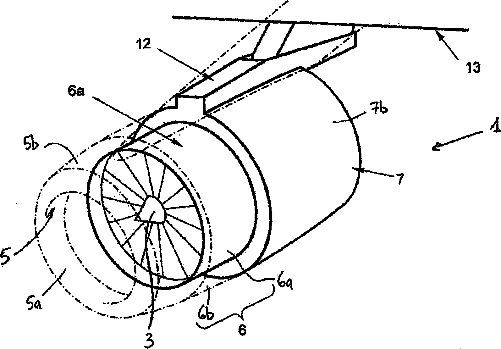
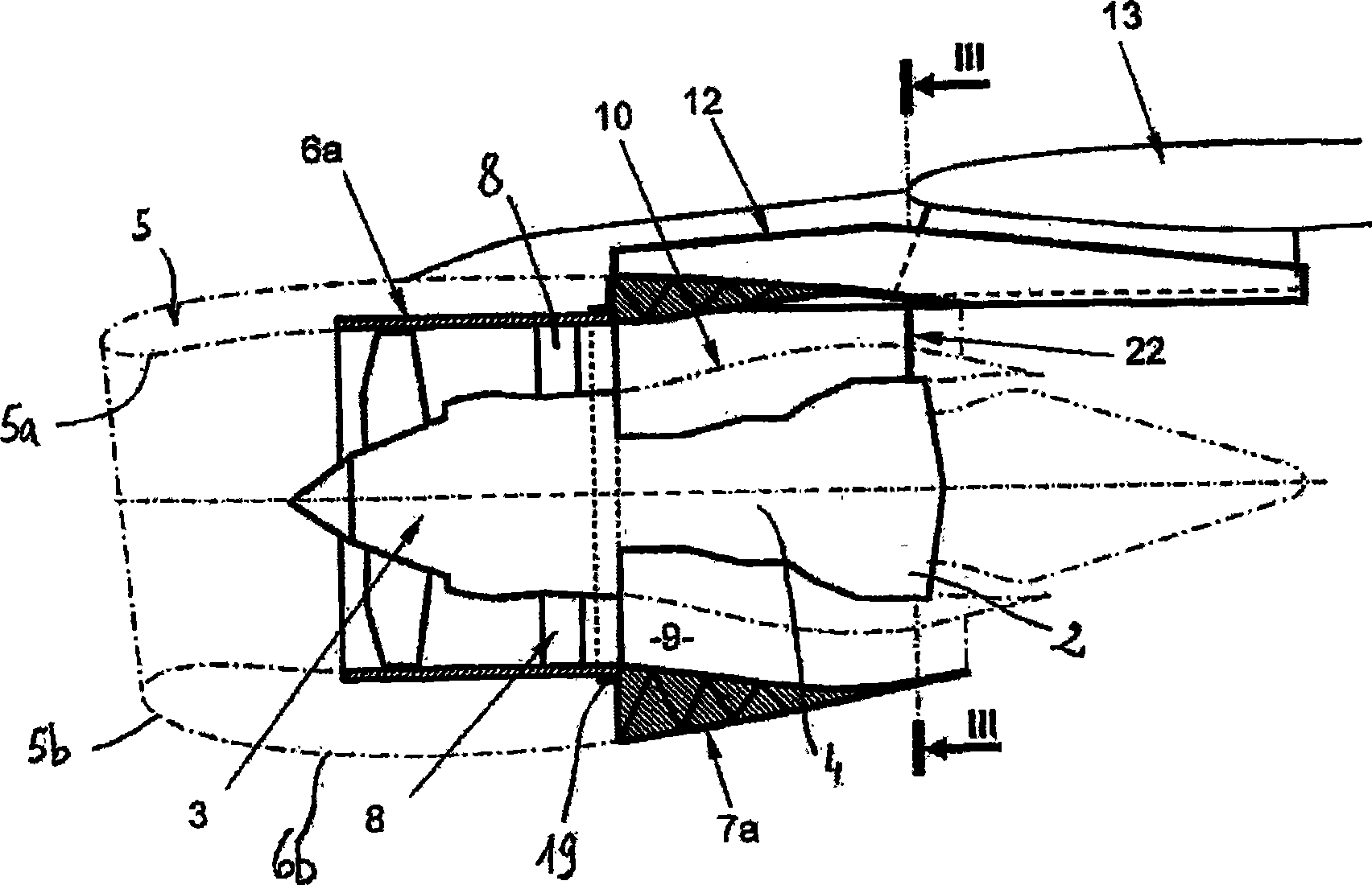
[0065] figure 1 and figure 2 A nacelle 1 for a bypass turbojet 2 is shown.

[0066] The nacelle 1 constitutes a tubular casing for bypassing the turbojet engine 2 and for guiding it through the air flow generated by the blades of the fan 3 , that is to say the hot air flow through the combustion chamber 4 of the turbojet engine 2 and out of the turbojet engine 2 of cold air.

[0067] The nacelle 1 has a structure comprising a front part forming an air intake structure 5 , a central part 6 surrounding a fan 3 of the turbojet engine 2 , and a rear part 7 surrounding the turbojet engine 2 . The air intake structure 5 has an inner surface 5a designed to guide the intake air and an outer rectifying surface 5b. The central part 6 comprises on the one hand an inner casing 6a enclosing the fan 3 of the turbojet engine 2 and on the other hand an outer fairing 6b of the casing extending the outer surface 5b of the air intake structure 5 .

[0068] The housing 6a is connected to the...


PUM


Abstract

The invention relates to bypass turbojet engine nacelle, the nacelle (1) comprises an air intake (5) upstream of the turbojet engine (2), a middle section (6) an internal casing (6a) of which is intended to surround a fan (3) of the turbojet engine (2), and a downstream section (7) comprising an external structure (7a) which is rigidly connected to a downstream part of the casing (6a) of the fan (3) so as to support the turbojet engine (2) and has means of attachment to a strut (12) intended to be connected to a fixed structure (13) of an aeroplane.

Description

technical field [0001] The invention relates to a nacelle for a bypass turbojet engine, and a propulsion assembly comprising the nacelle. Background technique [0002] The aircraft is propelled by several turbojet engines, each turbojet engine is housed in a nacelle which also houses a set of associated actuating means (such as thrust reversal means) Various functions can be realized when running or stopping. [0003] The nacelle generally has a tubular structure comprising the air intake structure upstream of the turbojet engine, a central part arranged to enclose the fan of the turbojet engine, and downstream accommodating thrust reversers and designed to enclose the combustion chamber of the turbojet engine section, which usually ends in the exhaust nozzle, the outlet of which is located downstream of the turbojet engine. [0004] A modern nacelle is designed to accommodate a bypass turbojet engine, which is able to generate a hot air flow (also called main air flow) or...

Claims


Application Information

Patent Timeline
IPC IPC(8): B64D27/18
CPCY02T50/44Y02T50/672B64D27/18B64D2027/264Y02T50/40B64D27/402
Inventor 居·伯纳德·沃琪尔热罗姆·科利埃帕特里斯·代诺尔弗朗索瓦·孔泰尼克拉斯·伊莱奥皮埃尔·阿兰·舒阿尔纪尧姆·勒福尔
Owner AIRCELLE
Why Eureka
Try Eureka