Backlight module and liquid crystal display

A technology of backlight module and liquid crystal display panel, which is applied to static indicators, semiconductor devices of light-emitting elements, instruments, etc., can solve the problems of cumbersome maintenance methods and so on.

Inactive Publication Date: 2009-09-09
AU OPTRONICS CORP
View PDF0 Cites 7 Cited by
  • Summary
  • Abstract
  • Description
  • Claims
  • Application Information

AI Technical Summary

Problems solved by technology

[0006] However, when some of these LED elements 135 are damaged, maintenance personnel must sequentially dismantle the front frame 110, the liquid crystal display panel 120, these optical films 131, the plastic frame 132, and the reflector 133 before replacing the damaged LED elements. 135
Therefore, the maintenance method of the backlight module 130 of the traditional liquid crystal display 100 is relatively cumbersome.

Method used


Image

  • Backlight module and liquid crystal display
  • Backlight module and liquid crystal display
  • Backlight module and liquid crystal display

Examples


no. 1 example

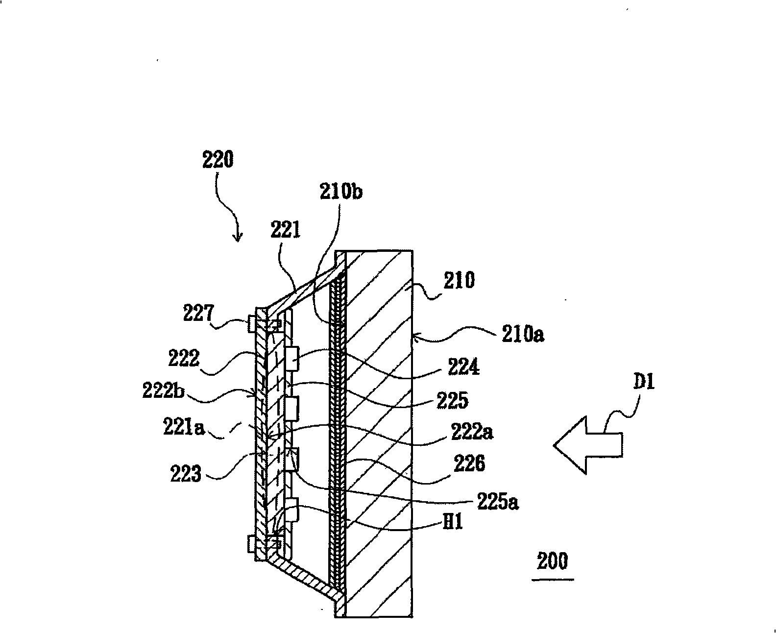
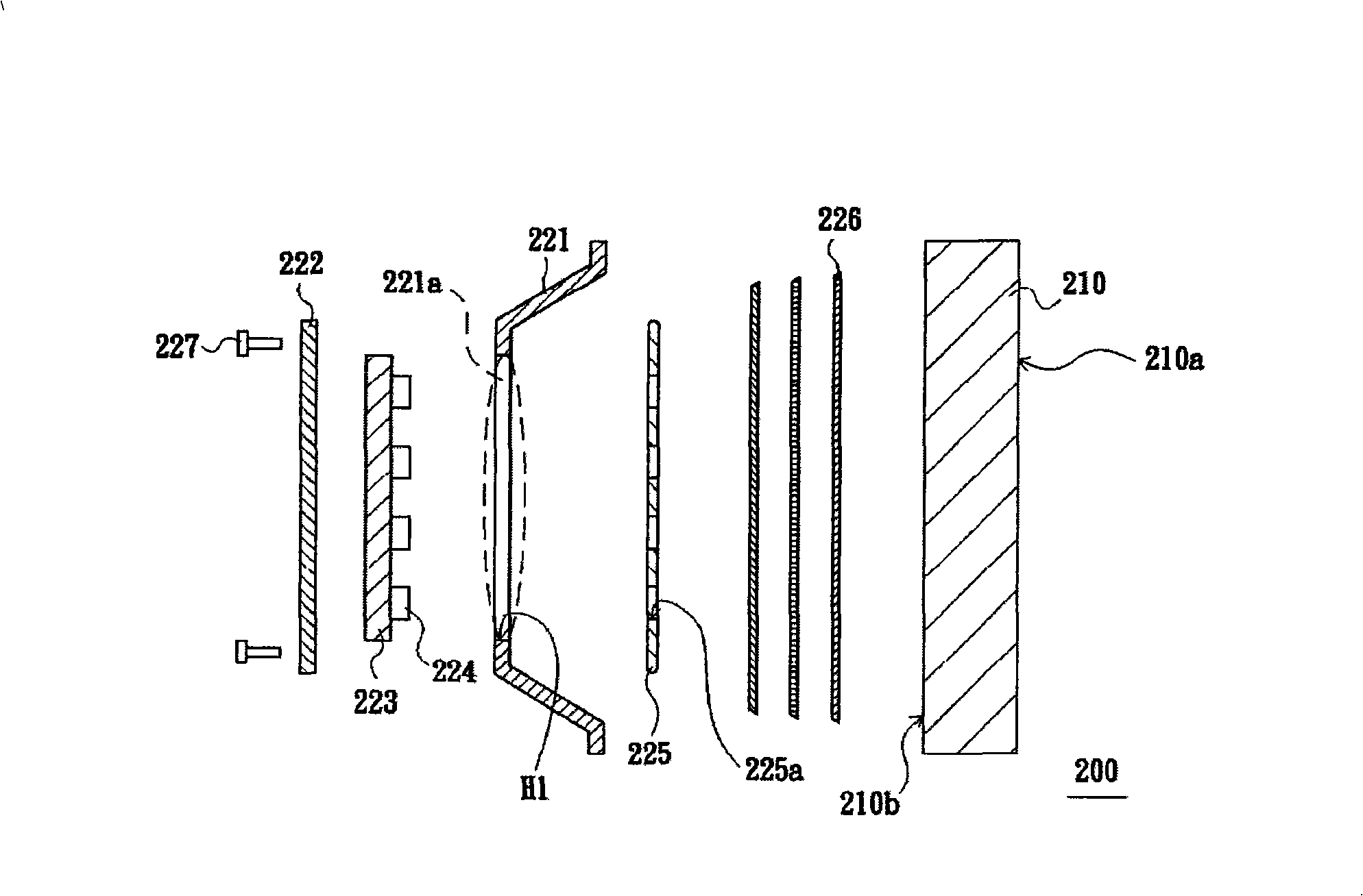
[0066] Figure 2A A schematic cross-sectional view of a liquid crystal display according to the first embodiment of the present invention is shown. Figure 2B show Figure 2A Schematic diagram of an exploded LCD display. Please refer to Figure 2A versus Figure 2B The liquid crystal display 200 of this embodiment includes a liquid crystal display panel 210 and a backlight module 220. The backlight module 220 includes a back plate 221, a carrier 222, a circuit board 223, a light-emitting element 224 (schematically shown in FIG. 2), a reflective sheet 225, a plurality of optical films 226, and a fixing member 227 (schematically shown in FIG. 2). Multiple). The back plate 221 has a through hole area 221a, and the through hole area 221a has a through hole H1. The back plate 221 is disposed in the non-display area 210 b of the liquid crystal display panel 210.

[0067] The carrier 222 is, for example, a plate body, which is disposed on the back plate 221 and has a first surface 222a ...

no. 2 example

[0072] Figure 3A A schematic cross-sectional view of a liquid crystal display according to the second embodiment of the present invention is shown. Figure 3B show Figure 3A Schematic diagram of the rear view of the backlight module. Please refer to Figure 3A versus Figure 3B The difference between the liquid crystal display 300 of the second embodiment and the liquid crystal display 200 of the first embodiment is that the supporting member 322 of the backlight module 320 of the second embodiment is pivotally connected to the back plate 321.

[0073] In detail, the circuit board 323 includes a first body 323a and a second body 323b. Some of the light-emitting elements 324 are disposed on the first body 323a, and some of the light-emitting elements 324 are disposed on the second body 323b. The carrier 322 includes a third body 322a and a fourth body 322b. The first body 323 a and the second body 323 b of the circuit board 323 are respectively disposed on the third body 322 a a...

no. 3 example

[0076] Figure 4A A schematic cross-sectional view of a liquid crystal display according to the third embodiment of the present invention is shown. Please refer to Figure 4A The backlight module 420 of the liquid crystal display 400 of the third embodiment includes a plurality of fixing members 428 (for example, screws) and a plurality of fixing members 429 (for example, screws). The circuit board 423 is detachably disposed between the back plate 421 and the carrier 422. The assembling method of the backlight module 420 of this embodiment is as follows. First, the circuit board 423 is fixed to the back plate 421 by these fixing members 428. Then, the supporting member 422, which is a board body, is fixed to the circuit board 423 and the back plate 421 by the fixing members 429. Generally speaking, the circuit board is fixed between the back plate 421 and the carrier 422 by these fixing members 428 and 429.

[0077] The carrier 422 of this embodiment can be designed as a plate bo...


PUM


Abstract

The invention provides a backlight module which comprises a backboard, a bearing part, a circuit board and a luminous element. The backboard is provided with a punch block. The bearing part is arranged on the backboard. The circuit board is arranged on the bearing part. The luminous element is arranged on the circuit board and is corresponding to the punch block. A liquid crystal display comprises a liquid crystal display panel, the backlight module and a cover body. The liquid crystal display panel is provided with a display area and a non-display area, wherein, the display area and the non-display area are opposite to each other. The backlight module comprises the backboard, the circuit board and the luminous element. The backboard is arranged on the display area and is provided with the punch block corresponding to the non-display area. The luminous element is arranged on the circuit board and is corresponding to the punch block. The cover body is arranged on the liquid crystal display panel. The cover body is provided with a surface and covers the punch block. The surface of the cover body faces the punch block and the non-display area. And the circuit board is arranged on the surface. The maintenance way of the backlight module is convenient.

Description

Technical field [0001] The present invention relates to a backlight module, and particularly relates to a liquid crystal display. Background technique [0002] Please refer to figure 1 , Which shows a three-dimensional exploded schematic diagram of a conventional liquid crystal display. A conventional liquid crystal display (LCD) 100 includes a front frame 110, a liquid crystal display panel (LCD panel) 120, and a backlight module 130. [0003] The backlight module 130 includes a plurality of optical films 131, a bezel 132, a reflective sheet 133, a circuit board 134, and a plurality of light emitting diode elements (LEDs). element 135 and bottom plate 136. The light-emitting diode elements 135 are disposed on the circuit board 134 and are electrically connected to the circuit board 134. The reflection sheet 133 has a plurality of through holes 133a. The reflective sheet 133 is disposed on the circuit board 134, and the light emitting diode elements 135 respectively pass through...

Claims


Application Information

Patent Timeline
Patent Type & Authority Applications(China)
IPC IPC(8): F21S8/00F21V21/00F21V19/00F21V17/00G02F1/133G02F1/13357F21Y101/02F21Y103/10F21Y115/10
Inventor 傅世泽张韶崴粘松木魏肇治
Owner AU OPTRONICS CORP
Why Eureka
Try Eureka