Supercharge Your Innovation With Domain-Expert AI Agents!

Protection circuit for controller

A technology for protecting circuits and controllers, applied in the direction of protection against overvoltage, etc., can solve the problem of high cost, achieve the effect of reducing hardware cost and solving low resource utilization

Inactive Publication Date: 2011-12-21
BEIJING EASYSOLUTION ELECTRONICS
View PDF0 Cites 0 Cited by
  • Summary
  • Abstract
  • Description
  • Claims
  • Application Information

AI Technical Summary

Problems solved by technology

Usually, photoelectric isolation technology is used to realize switch input and high-speed technology input, and the cost is relatively good.

Method used


Image

  • Protection circuit for controller
  • Protection circuit for controller
  • Protection circuit for controller

Examples


Embodiment Construction

[0012] Exemplary embodiments of the present invention will be specifically described below with reference to the accompanying drawings.

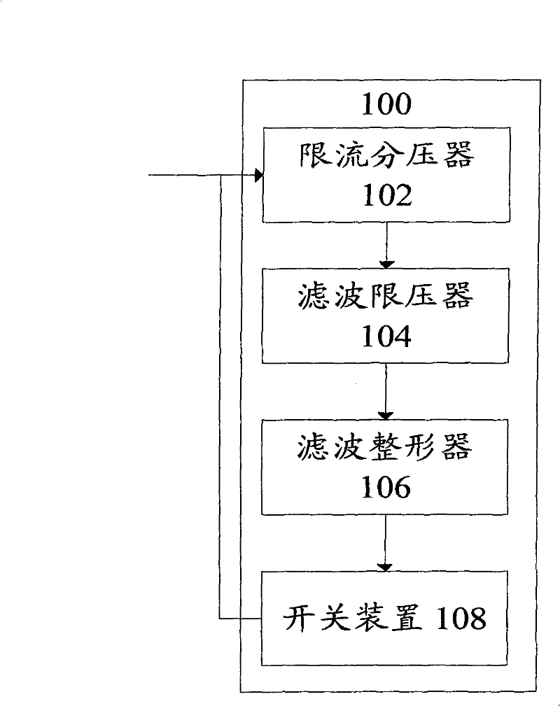
[0013] figure 1 A block diagram of a protection circuit according to an embodiment of the invention is shown.

[0014] The protection circuit 100 for the controller is used for over-current protection of the controller, including: a current-limiting voltage divider 102, which is used to limit the current and divide the input signal, and output the first signal; a filter voltage limiter 104, used performing filtering and current limiting processing on the first signal, and outputting a second signal; the filter shaper 106 is used to perform filtering and shaping processing on the second signal, and outputting a third signal; the switching device 108, in response to the first Three signals for switching action.

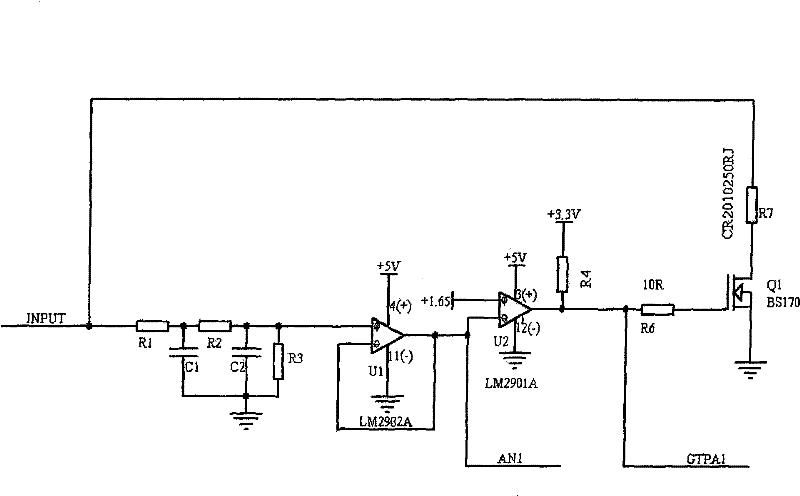
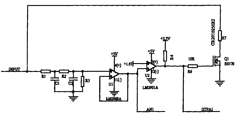
[0015] The specific circuit diagram is as figure 2 shown. The current-limiting voltage divider 102 includes a first resistor R1...


PUM


Abstract

The invention provides a protection circuit for a controller, which is used for over-current protection of the controller, including: a current-limiting voltage divider, used for current-limiting and voltage-dividing of an input signal, and outputting a first signal; A transformer, used to perform filtering and current limiting processing on the first signal, and output a second signal; a filter shaper, used to perform filtering and shaping processing on the second signal, and output a third signal; a switching device, responsive to the The third signal is used to perform the switching action. Through the circuit according to the invention, one input port can be realized for analog voltage input, 4-20mA current signal input, switch value input and high-speed counting input. The input signal is stable and reliable, the cost is low, and the wrong voltage input can be self-protected.

Description

technical field [0001] The present invention relates to protection circuits, and more particularly to protection circuits for controllers. Background technique [0002] In the engineering vehicle controller, the analog voltage input, 4-20mA current signal input, switch input and high-speed counting input are separated from the input ports, and the analog voltage input and 4-20mA current signal do not have voltage protection. Usually, photoelectric isolation technology is used to realize switch input and high-speed technical input, and the cost is relatively good. Therefore, in order to solve the technical problem of low utilization rate of input point resources, in order to reduce hardware cost, realize the technical effect of stable and reliable input point. A need exists for a protection circuit for a controller. Contents of the invention [0003] In order to solve at least one of the above technical problems, the present invention provides a protection circuit for a c...

Claims


Application Information

Patent Timeline
Patent Type & Authority Patents(China)
IPC IPC(8): H02H3/20
Inventor 朱关德王治国李亮高孝宛甘俊
Owner BEIJING EASYSOLUTION ELECTRONICS
Features
  • R&D
  • Intellectual Property
  • Life Sciences
  • Materials
  • Tech Scout
  • Unparalleled Data Quality
  • Higher Quality Content
  • 60% Fewer Hallucinations
Learn More